Tank Level Monitoring System
Tank Level Monitoring System
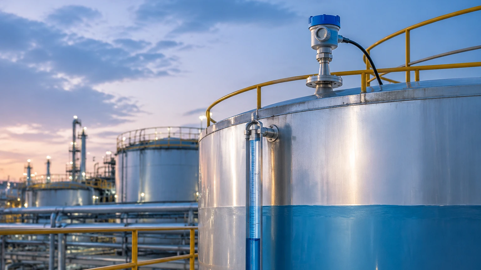
In industrial process control, a tank level monitoring system is a critical infrastructure component designed to provide real-time data on the volume or height of substances stored in vessels. These systems are essential for inventory management, overfill prevention, and process optimization across sectors such as water treatment, chemical processing, oil and gas, and food production.
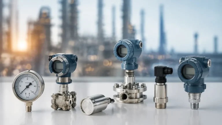
Reliable monitoring requires an integrated approach, combining high-precision sensors with robust data transmission and visualization tools. As a professional manufacturer, Welk provides a comprehensive range of instruments, including radar, ultrasonic, and hydrostatic sensors, ensuring that engineers can select the most appropriate technology for their specific environmental and media requirements. For a complete overview of available technologies, engineers often refer to the Main Page of technical catalogs to compare sensor specifications.
Measurement Principles and Technology Overview
Before selecting a tank level monitoring system, it is vital to understand the physics behind the various measurement technologies. Each method has distinct advantages depending on the physical properties of the media and the atmospheric conditions within the tank.
Radar Level Measurement (Non-Contact and Guided)
Radar technology utilizes electromagnetic waves, typically in the microwave frequency range (6GHz to 80GHz).
* Non-Contact Radar: The sensor emits a microwave signal toward the product surface. The signal reflects back to the sensor, and the system calculates the level based on the Time-of-Flight (ToF). Because electromagnetic waves do not require a medium for travel, radar is unaffected by vacuum, high pressure, or temperature fluctuations.
* Guided Wave Radar (GWR): This utilizes a probe (cable or rod) to guide the microwave signal to the surface. It is particularly effective for media with low dielectric constants or in tanks with heavy foam or internal obstructions.
Ultrasonic Level Measurement
Ultrasonic sensors function by emitting high-frequency sound pulses. The time taken for the echo to return from the liquid surface is measured.
* Principle: Distance = (Speed of Sound × Time) / 2.
* Application: Ideal for water and wastewater applications. However, because sound speed is affected by air temperature and density, integrated temperature compensation is required. It is generally not recommended for vacuum applications or environments with heavy dust and steam.
Hydrostatic Pressure Measurement
This method relies on the principle that the pressure at the bottom of a tank is directly proportional to the height of the liquid column above it.
* Formula: P = ρgh (where P is pressure, ρ is density, g is gravity, and h is height).
* Implementation: Submersible pressure transducers or flange-mounted transmitters are used. This is a highly reliable method for vented tanks containing liquids with a constant density.
Magnetic Level Gauges
Magnetic gauges use a float containing a high-intensity magnet that moves with the liquid level inside a bypass chamber. This magnet interacts with external flags (for visual indication) or a reed-chain transmitter (for electronic monitoring). This provides both a local mechanical readout and a remote signal for the tank level monitoring system.
Components of a Modern Tank Level Monitoring System
A functional monitoring system is more than just a sensor; it is a multi-layered architecture designed for data integrity.
1. Sensing Element: The primary instrument (Radar, Ultrasonic, etc.) that interacts with the media.
2. Signal Transmitter: Converts the raw sensor data into a standardized industrial signal. Common outputs include 4-20mA (analog), HART, Modbus RTU (RS485), or Foundation Fieldbus.
3. Local Display/Controller: Provides on-site visibility for operators and often includes relay outputs for high/low-level alarms.
4. Data Gateway and Integration: In modern facilities, data is fed into a PLC (Programmable Logic Controller), SCADA system, or a cloud-based platform for remote monitoring and historical data logging.
Technical Selection Table
Choosing the right technology requires balancing performance requirements with budget constraints. The following table provides a general engineering guideline for common industrial scenarios.
| Technology | Accuracy | Typical Range | Media Type | Key Advantage | Limitation |
| :— | :— | :— | :— | :— | :— |
| 80GHz Radar | ±1 mm (0.04 in) | Up to 120m (393 ft) | Liquids/Solids | Extremely precise; ignores steam/dust. | Higher initial cost. |
| Ultrasonic | ±0.25% of range | 0.5m – 15m (1.6 – 49 ft) | Water/Corrosives | Non-contact; cost-effective. | Affected by foam and vacuum. |
| Hydrostatic | ±0.1% to 0.5% | 1m – 200m (3.2 – 656 ft) | Clear Liquids | Simple installation; very stable. | Sensitive to density changes. |
| Magnetic Gauge | ±5 mm (0.2 in) | 0.3m – 6m (1 – 20 ft) | Clean Liquids | No power needed for visual check. | Mechanical parts can foul. |
| Level Switch | N/A (Point) | N/A | All types | Overfill protection. | Only detects specific points. |
Installation Considerations and Best Practices
Correct installation is as important as sensor selection. Even the most advanced tank level monitoring system will fail if the physical mounting is flawed.
Nozzle Placement and Obstructions
For non-contact sensors (Radar and Ultrasonic), the signal spreads in a cone shape. If the sensor is mounted too close to the tank wall or near internal structures like ladders, agitators, or heating coils, "false echoes" will occur.
* Rule of Thumb: Maintain a distance from the wall of at least 1/10th of the tank height.
* Beam Angle: Check the sensor's beam angle to ensure the signal path is clear of obstructions throughout the entire measurement range.
The "Dead Zone" (Blocking Distance)
All top-mounted sensors have a minimum distance they cannot measure, known as the dead zone or blocking distance. For ultrasonic sensors, this is usually 0.25m to 0.5m (10 to 20 inches). If the liquid enters this zone, the sensor may report an incorrect reading or enter an error state. Engineers must ensure the mounting nozzle height accounts for this limitation.
Environmental Factors
* Vapor and Condensation: In chemical tanks, condensation can form on the sensor face. Some radar sensors feature PTFE-encapsulated antennas to shed moisture.
* Turbulence: If the tank has an agitator, the surface will be turbulent. Hydrostatic sensors or guided-wave radar are often preferred here as they are less affected by surface ripples.
* Tank Venting: Hydrostatic sensors in sealed tanks require a differential pressure setup or a vented cable to compensate for changes in atmospheric pressure.
Common Risks and Limitations
While modern systems are highly reliable, certain risks must be mitigated during the design phase:
1. Media Buildup: In wastewater or slurry applications, material can build up on the sensor. Non-contact radar is generally more resistant to this than mechanical or ultrasonic options.
2. Dielectric Constant (εr): Radar signals rely on the dielectric constant of the material. If the εr is very low (e.g., certain oils or liquefied gases), the signal reflection may be too weak. In these cases, guided wave radar or hydrostatic transmitters are better choices.
3. Signal Interference: In large plants, electromagnetic interference (EMI) from high-power pumps or variable frequency drives (VFDs) can distort 4-20mA signals. Using shielded cables and proper grounding is mandatory.
Project Confirmation Checklist
Before finalizing a purchase or installation plan for a tank level monitoring system, project managers should confirm the following data points:
* Media Profile: What is the chemical composition, density, and dielectric constant?
* Process Conditions: What are the maximum and minimum operating temperatures and pressures?
* Tank Geometry: What is the total height, diameter, and the location of all internal obstructions?
* Output Requirements: Does the facility require local display, 4-20mA, Modbus, or wireless transmission?
* Safety Certifications: Does the environment require ATEX/IECEx explosion-proof ratings or SIL safety integrity levels?
Frequently Asked Questions (FAQ)
Q: Can one sensor work for both liquids and solids?
A: High-frequency radar (80GHz) is often capable of measuring both, but the configuration differs. Solids often require a swiveling flange to aim the beam at the material's angle of repose.
Q: How often do these systems require calibration?
A: This depends on the technology. Hydrostatic sensors may drift over years and require periodic zero-point checks. Radar and ultrasonic sensors are generally "set and forget" unless the media properties or tank internals change.
Q: What is the benefit of a redundant system?
A: For critical applications like fuel storage or toxic chemical processing, using two different technologies (e.g., a radar sensor for continuous level and a tuning fork switch for high-level alarm) provides a fail-safe mechanism against hardware failure.
Q: How does foam affect the measurement?
A: Thick, dense foam can absorb ultrasonic and radar signals. Guided wave radar is typically the most effective solution for penetrating foam to reach the true liquid surface.
For engineers seeking detailed technical drawings and performance curves for these instruments, the Main Page of the Welk product catalog serves as a primary reference for system integration and hardware selection. Proper planning and technology alignment ensure that the tank level monitoring system provides the accuracy and longevity required for industrial operations.