Tank Monitor
Tank Monitor
In modern industrial processing, a tank monitor is more than a simple gauge; it is a critical component of inventory management, safety protocols, and process automation. Whether managing bulk chemicals, water treatment facilities, or oil and gas storage, the ability to accurately track the volume and level of media in real-time is essential for operational efficiency. Industrial tank monitoring systems integrate sensors, transmitters, and control interfaces to provide data that prevents overfills, ensures continuous supply, and optimizes logistics.
Selecting the appropriate technology for a tank monitor requires a deep understanding of the physical properties of the media, the environmental conditions of the vessel, and the required precision of the data. This guide examines the primary measurement principles used in industrial level sensing, provides selection criteria, and outlines best practices for installation and maintenance.
Core Measurement Technologies for Tank Monitoring
Industrial level measurement instruments generally fall into two categories: non-contact and contact-based. Each principle has distinct advantages depending on the application environment.
Radar Level Measurement (Non-Contact)
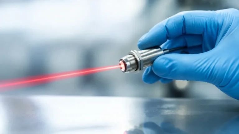
Radar technology is widely considered the gold standard for high-precision tank monitoring, particularly in challenging environments. It operates on the principle of electromagnetic wave reflection. The sensor emits a high-frequency signal (typically in the 26 GHz or 80 GHz range) toward the product surface. The signal reflects off the media and returns to the sensor.
There are two primary types of radar measurement:
1. Pulse Radar: Measures the time it takes for a short microwave pulse to travel to the surface and back (Time of Flight).
2. FMCW (Frequency Modulated Continuous Wave): Emits a continuous signal with a varying frequency. The difference in frequency between the emitted and received signal is proportional to the distance.
Radar is highly effective because microwaves are largely unaffected by temperature fluctuations, vacuum, or high pressure. Modern 80 GHz radar units offer a narrow beam angle, which is ideal for tanks with internal obstructions like agitators or heating coils.
Ultrasonic Level Measurement
Ultrasonic sensors are a cost-effective non-contact solution for many liquid applications. These devices emit high-frequency sound waves (ultrasound) that bounce off the liquid surface. The sensor calculates the distance based on the time interval between the emission and the reception of the echo.
While highly versatile, ultrasonic measurement is dependent on the speed of sound, which varies with air temperature. Most industrial ultrasonic tank monitors include integrated temperature compensation to maintain accuracy. However, they are sensitive to heavy foam, heavy dust, or vapor layers that can absorb or scatter the sound waves, leading to signal loss.
Hydrostatic Level Transmitters
Hydrostatic measurement is a contact-based method that relies on the relationship between liquid height and pressure. According to the hydrostatic law, the pressure at the bottom of a tank is directly proportional to the height of the liquid column and its density ($P = \rho \cdot g \cdot h$).
For vented (atmospheric) tanks, a submersible pressure transducer or a flange-mounted transmitter measures the pressure exerted by the liquid. In pressurized vessels, a differential pressure (DP) transmitter is used to subtract the head pressure (gas phase) from the total pressure at the bottom. This method is exceptionally reliable for clean liquids and is widely used in water and wastewater management.
Magnetic Level Gauges
Magnetic level gauges provide both a visual indication and the possibility for remote electronic monitoring. They consist of a bypass chamber connected to the side of the tank. Inside the chamber, a float containing a permanent magnet moves up and down with the liquid level. Outside the chamber, a series of bi-color flaps or a magnetic tracker follows the float, providing a clear visual representation.
To integrate this into a digital tank monitor system, a magnetostrictive transmitter or a reed switch string can be mounted to the outside of the chamber, converting the float position into a 4-20mA or digital signal. This technology is preferred for high-pressure or hazardous media where direct contact with the electronic sensor must be minimized.
Technology Selection and Comparison Table
Choosing the right sensor involves balancing performance requirements with budget constraints. The following table compares the most common technologies used in industrial tank monitoring.
| Technology | Accuracy | Max Range | Media Suitability | Typical Applications |
| :— | :— | :— | :— | :— |
| 80GHz Radar | ±1 mm (0.04 in) | Up to 120m (393 ft) | Liquids, Solids, Corrosives | Chemical, Oil & Gas, Silos |
| Ultrasonic | ±0.25% of range | Up to 15m (49 ft) | Water, Wastewater, Acids | Sump pits, Water storage |
| Hydrostatic | ±0.1% to 0.5% | Varies by pressure | Clean liquids, Slurries | Reservoirs, Fuel tanks |
| Magnetic Gauge | ±5 mm (0.2 in) | Up to 6m (20 ft) | Clean liquids, High pressure | Boilers, Chemical reactors |
| Level Switch | Point detection | N/A | Almost all media | Overfill protection, Pump control |
Application-Specific Selection Criteria
When designing a tank monitor system, engineers must evaluate several factors beyond the measurement principle itself:
1. Media Properties: Is the liquid corrosive, viscous, or prone to coating? Radar is excellent for corrosives as it can measure through plastic windows or PTFE flanges. Hydrostatic sensors require materials (like Hastelloy or Ceramic) compatible with the fluid.
2. Vessel Geometry: Tall, narrow silos require the focused beam of high-frequency radar. Shallow sumps are often well-served by ultrasonic sensors.
3. Process Conditions: High temperatures (above 200°C / 392°F) or high pressures (above 40 bar / 580 psi) typically necessitate specialized radar or magnetic level gauges.
4. Communication Requirements: Modern systems often require integration into a PLC or SCADA system via 4-20mA HART, RS485 Modbus, or Foundation Fieldbus. For remote sites, cellular-based tank monitors are increasingly popular.
For detailed technical specifications and support in selecting the right instrument for your specific process, you can Review product options and application support on the Welk Main Page.
Installation and Engineering Best Practices
Correct installation is as vital as selecting the right sensor. Even the most advanced radar or ultrasonic tank monitor will fail if positioned incorrectly.
* Avoid the Dead Zone: Every non-contact sensor has a "dead zone" or "blocking distance" near the sensor face where measurement is impossible. Ensure the maximum possible liquid level does not enter this zone.
* Nozzle Geometry: For radar and ultrasonic sensors, the nozzle should be as short and wide as possible to prevent signal interference from the nozzle walls. If a long nozzle is required, the sensor must be configured to ignore the internal reflections.
* Obstruction Clearance: Sensors should be mounted away from inlet pipes, ladders, and agitators. If obstructions are unavoidable, many modern transmitters offer "false echo suppression" software to map out and ignore these static reflections.
* Positioning: Sensors should generally not be mounted in the center of a domed tank, as the dome can act as a parabolic dish, concentrating unwanted reflections. They should also be kept away from the tank wall to avoid side-lobe interference.

Limitations and Common Risks
While modern tank monitors are highly sophisticated, they are not immune to environmental challenges:
* Foam and Turbulence: Thick foam can absorb ultrasonic and radar signals. In such cases, a guided wave radar (using a probe) or a hydrostatic sensor may be more effective.
* Vapor and Condensation: Heavy steam or chemical vapors can slow down ultrasonic waves, leading to errors. Radar is generally immune to this, but heavy condensation on the sensor face can still attenuate the signal.
* Density Changes: Hydrostatic sensors measure weight, not volume. If the temperature of the liquid changes significantly, its density changes, which will alter the level reading even if the actual volume remains constant.
* Build-up: In sticky or crystallizing media, material can build up on the sensor or the float. Non-contact radar is often the best defense against this, but periodic cleaning may still be required in extreme cases.
Maintenance and Troubleshooting
A robust maintenance schedule ensures the longevity of the tank monitoring system.
1. Calibration Verification: Sensors should be checked annually against a manual tape measure or a known reference point.
2. Signal Strength Monitoring: Most digital transmitters provide a signal-to-noise ratio or echo strength value. A declining value often indicates build-up on the sensor or a change in the media's reflective properties.
3. Seal Integrity: For hydrostatic and magnetic gauges, checking the integrity of seals and gaskets is crucial to prevent leaks and protect the internal electronics.
Frequently Asked Questions (FAQ)
Q: Can one tank monitor be used for different liquids?
A: It depends on the technology. Radar and ultrasonic sensors measure the distance to the surface and are generally independent of the liquid type (as long as the dielectric constant or reflectivity is sufficient). Hydrostatic sensors, however, must be recalibrated if the liquid density changes.
Q: What is the difference between a level transmitter and a level switch?
A: A level transmitter provides continuous measurement (e.g., 0-100% full), whereas a level switch provides point detection (e.g., "tank is full" or "tank is empty"). Most tank monitor systems use a transmitter for inventory and a separate switch for high-level safety alarms.
Q: How do I measure level in a tank with a vacuum?
A: Radar is the preferred choice for vacuum applications because electromagnetic waves do not require a medium (like air) to travel. Ultrasonic sensors will not work in a vacuum.
Q: What is the maximum distance a tank monitor can be from the control room?
A: Using a standard 4-20mA loop, signals can typically travel up to 1,000 meters (3,280 ft) without significant degradation. For longer distances, digital protocols like RS485 or wireless telemetry are used.
Conclusion
Implementing an effective tank monitor system is a foundational step toward industrial safety and process optimization. By understanding the physics behind radar, ultrasonic, and hydrostatic measurement, engineering teams can select the tool that best fits their specific environmental constraints. Proper installation, mindful of dead zones and obstructions, combined with a proactive maintenance strategy, ensures that the data driving your process remains accurate and reliable for years to come.