Flowmeter 1 2
Flowmeter 1 2
In the landscape of industrial process control, the selection of instrumentation for small-bore piping is a critical task that directly impacts the accuracy of chemical dosing, water treatment, and laboratory automation. A "flowmeter 1 2" typically refers to a flow measurement device designed for a 1/2-inch (DN15) nominal pipe size. Despite the relatively small dimensions, these instruments must handle complex fluid dynamics and provide high-precision data to ensure system efficiency. This guide examines the technical principles, selection criteria, and installation requirements for 1/2-inch flowmeters in professional B2B applications.
Measurement Principles for 1/2-Inch Flowmeters
Before selecting a flowmeter for a 1/2-inch line, it is essential to understand the underlying physics governing different measurement technologies. Because the internal diameter is small—approximately 12.7 mm to 15 mm depending on the pipe schedule—fluid velocity and turbulence behave differently than in large-scale headers.
Electromagnetic Flowmeters (Magmeters)
Electromagnetic flowmeters operate based on Faraday’s Law of Electromagnetic Induction. This principle states that a conductor (the fluid) moving through a magnetic field generates a voltage proportional to its velocity. For a 1/2-inch magmeter, the formula $E = B \cdot v \cdot D$ applies, where $E$ is the induced voltage, $B$ is the magnetic field strength, $v$ is the fluid velocity, and $D$ is the distance between electrodes (the pipe diameter).
In small-bore applications, magmeters are highly valued because they offer an unobstructed flow path, resulting in zero pressure drop. However, they require the fluid to have a minimum conductivity, typically $\geq 5$ μS/cm.
Turbine Flowmeters
Turbine meters utilize a multi-bladed rotor suspended in the fluid stream. As the fluid passes through the 1/2-inch housing, it causes the rotor to spin at a speed proportional to the flow rate. A pickup coil detects the movement of the rotor blades and converts it into an electrical pulse. These are excellent for low-viscosity, clean liquids where high precision is required, though they are susceptible to wear if the fluid contains abrasives.
Ultrasonic Flowmeters (Transit-Time)
Ultrasonic meters for 1/2-inch pipes often use the transit-time principle. Two transducers send ultrasonic signals back and forth through the fluid. The signal traveling with the flow moves faster than the signal traveling against it. The difference in time is proportional to the flow velocity. In small pipes, signal path length is short, so high-frequency transducers are often employed to maintain accuracy.
Vortex Flowmeters
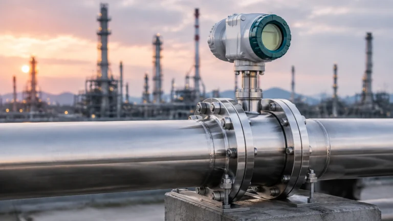
Vortex meters rely on the Von Karman effect. A bluff body placed in the flow stream creates alternating vortices. The frequency of these vortices is directly proportional to the fluid velocity. While robust, vortex meters for 1/2-inch lines require a minimum Reynolds number to function correctly, meaning they may not be suitable for very low-flow applications.
Technical Selection Criteria for DN15 (1/2") Systems
Choosing the right flowmeter 1 2 involves more than just matching the pipe size. Engineers must evaluate the fluid properties and the operational environment to avoid premature failure or inaccurate readings.
Selection Table: Comparison of 1/2-Inch Flow Technologies
| Technology | Fluid Type | Typical Accuracy | Pressure Drop | Minimum Velocity |
| :— | :— | :— | :— | :— |
| Electromagnetic | Conductive Liquids | ±0.5% | Negligible | 0.1 m/s |
| Turbine | Clean, Low-Viscosity | ±0.25% | Moderate | 0.3 m/s |
| Ultrasonic | Clean/Slightly Dirty | ±1.0% | None | 0.5 m/s |
| Vortex | Steam, Gas, Liquid | ±1.0% | Moderate | 2.0 m/s (Liquid) |
| Variable Area | Gas, Liquid | ±2.0% – 5.0% | Low | N/A (Visual) |
Fluid Compatibility and Material Science
For 1/2-inch applications in the chemical or pharmaceutical sectors, material compatibility is paramount. Common housing materials include 316L stainless steel, while liners for magmeters may include PTFE (Teflon) or PFA to resist corrosive media. In water treatment, PVC or PVDF bodies are frequently used for cost-effective chemical skid integration.
Flow Range and Turndown Ratio
The turndown ratio (the ratio of maximum to minimum measurable flow) is a vital metric. A 1/2-inch turbine meter might offer a 10:1 turndown, meaning if its max flow is 50 L/min, it can accurately measure down to 5 L/min. Magmeters often provide superior turndown ratios, sometimes reaching 100:1, which is critical for processes with highly variable flow rates.
Installation Guidelines and Best Practices
Proper installation is the most significant factor in the long-term performance of a flowmeter 1 2. Small-diameter pipes are prone to localized turbulence caused by valves, elbows, and pumps.
1. Straight Pipe Runs: To ensure a fully developed flow profile, most 1/2-inch meters require a specific length of straight pipe upstream and downstream. A common rule of thumb is "10D Upstream and 5D Downstream." For a 1/2-inch (12.7 mm) pipe, this means 127 mm of straight pipe before the meter and 63.5 mm after it.
2. Orientation: For liquid applications, the pipe must remain full at all times. Vertical installation with upward flow is often preferred to prevent air bubbles from being trapped in the meter body, which would cause significant errors in ultrasonic and electromagnetic readings.
3. Grounding: Specifically for electromagnetic meters, proper grounding is essential to eliminate electrical noise. In plastic piping systems, grounding rings must be installed on either side of the 1/2-inch meter to provide a reference point for the fluid potential.
4. Avoid Cavitation: Ensure the downstream pressure is high enough to prevent the fluid from vaporizing as it passes through any restrictions in the meter, particularly with turbine or vortex technologies.
Limitations and Common Challenges
While 1/2-inch flowmeters are versatile, they face specific limitations in industrial environments:
* Viscosity Sensitivity: Mechanical meters like turbines are highly sensitive to changes in fluid viscosity. If the liquid thickens due to temperature drops, the rotor will slow down, leading to under-reporting of the flow.
* Scaling and Buildup: In small-bore pipes, even a thin layer of scale (1–2 mm) significantly changes the internal cross-sectional area. Since flowmeters calculate volume based on area ($Q = A \cdot v$), this buildup results in substantial measurement drift.
* Signal-to-Noise Ratio: In 1/2-inch ultrasonic applications, the proximity of the transducers to each other can lead to signal interference or "ringing," requiring sophisticated digital signal processing to filter out noise.

The Synergy Between Flow and Level Measurement
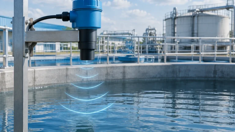
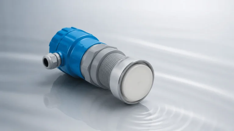
In many industrial processes, flow measurement does not exist in a vacuum. It is often paired with level measurement to provide a complete mass balance of a system. For instance, in a chemical blending tank, a 1/2-inch flowmeter might measure the precise amount of additive being injected, while a radar or ultrasonic level transmitter monitors the total volume in the vessel.
Companies like Welk specialize in providing these integrated solutions. For engineers looking to optimize their entire process loop, exploring the Main Page for advanced level measurement technology is a logical next step. Understanding how the inflow (measured by a flowmeter 1 2) correlates with the change in tank level allows for redundant verification and leak detection, which are essential for safety-critical applications.
Frequently Asked Questions (FAQ)
Q: Can I use a 1/2-inch flowmeter for steam measurement?
A: Yes, but you must select a technology capable of handling high temperatures and phase changes. Vortex flowmeters are the standard choice for 1/2-inch steam lines, provided the flow velocity is high enough to shed vortices.
Q: What is the typical flow rate for a 1/2-inch pipe?
A: In industrial water applications, a 1/2-inch pipe typically handles between 5 and 40 Liters per minute (L/min), assuming a velocity of 0.5 to 4.0 meters per second. However, this depends on the allowable pressure drop for your specific process.
Q: How often should a flowmeter 1 2 be calibrated?
A: For standard water applications, annual calibration is typical. For high-precision chemical dosing or regulated industries (like food and pharma), semi-annual calibration may be required to ensure compliance and accuracy.
Q: Do 1/2-inch flowmeters require a strainer?
A: If you are using a turbine or gear meter, a 50-mesh or finer strainer is highly recommended to prevent particulates from damaging the internal moving parts. Electromagnetic and ultrasonic meters are more tolerant of solids but still benefit from clean fluid to prevent liner abrasion.
Conclusion
The implementation of a flowmeter 1 2 requires a disciplined approach to engineering selection. By prioritizing the measurement principle that matches the fluid characteristics and adhering to strict installation standards, operators can achieve reliable, long-term data. Whether used for simple water monitoring or complex chemical injection, these small-bore instruments are the backbone of precise industrial automation. For those managing complex tank systems, combining these flow insights with high-quality level instrumentation ensures a robust and efficient production environment.