Ultrasonic Level Meter Manual
Ultrasonic Level Meter Manual: A Comprehensive Engineering Guide
In industrial process control, the accuracy of liquid and solid level measurement is paramount. Among the various technologies available, ultrasonic sensors have become a preferred choice due to their non-contact nature and versatility. However, the successful deployment of these instruments relies heavily on the technical documentation provided by the manufacturer. An ultrasonic level meter manual serves as more than just a set of instructions; it is a critical engineering reference that defines the operational boundaries, installation constraints, and calibration parameters necessary for reliable performance.
For engineers and plant operators, understanding the nuances within an ultrasonic level meter manual is the first step toward optimizing process efficiency. This guide explores the fundamental principles, selection criteria, and technical requirements typically found in high-quality documentation for Ultrasonic Level Meters.
1. Measurement Principles and Technology Overview
Before diving into the specifics of a manual, it is essential to understand how these devices function. Ultrasonic level meters operate on the "Time-of-Flight" (ToF) principle.
The Physics of Sound Reflection
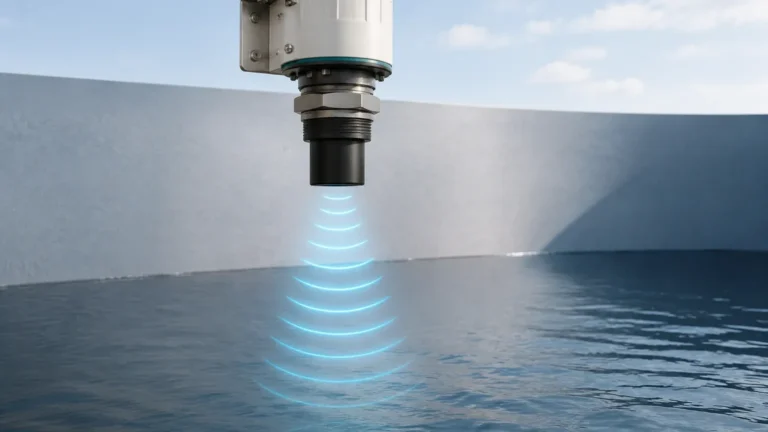
The device's transducer emits a high-frequency acoustic pulse (usually between 20 kHz and 200 kHz). This sound wave travels through the air, strikes the surface of the medium (liquid or solid), and reflects back to the transducer. The instrument then calculates the distance between the sensor and the surface using the following formula:
Distance = (Speed of Sound × Time) / 2
Since the distance from the sensor to the bottom of the tank (the "zero point") is known, the device subtracts the measured distance from the total height to determine the actual level of the material.
Temperature Compensation
The speed of sound in air is approximately 344 m/s at 20°C, but it changes by roughly 0.17% per degree Celsius. To maintain accuracy, a professional ultrasonic level meter manual will specify the presence of an internal temperature sensor. This sensor allows the meter to automatically compensate for fluctuations in the ambient air temperature within the vessel, ensuring that the calculated distance remains precise regardless of thermal changes.
2. Key Technical Specifications to Verify
When reviewing a manual, the technical specification table is the most critical section for hardware selection. Engineers must confirm that the instrument's capabilities align with the application's physical environment.
| Feature | Description | Typical Industrial Range |
| :— | :— | :— |
| Measuring Range | The maximum distance the pulse can travel and return. | 0.3m to 30m (1ft to 100ft) |
| Dead Zone | The area directly below the sensor where measurement is impossible. | 0.2m to 0.6m (8" to 24") |
| Accuracy | The margin of error under standard conditions. | ±0.25% to ±0.5% of full scale |
| Output Signals | How the data is transmitted to the control system. | 4-20mA, RS485 (Modbus), HART |
| Beam Angle | The width of the ultrasonic cone. | 5° to 12° |
| Protection Class | The environmental sealing of the housing. | IP65, IP66, or IP68 |
| Process Pressure | The pressure limits of the environment. | -0.02 MPa to 0.1 MPa |
Understanding the Dead Zone (Blocking Distance)
Every ultrasonic level meter has a "Dead Zone" (also known as the blocking distance). This is the region immediately adjacent to the transducer face where the sensor cannot receive a return signal because it is still vibrating from the transmission pulse. A manual will explicitly state this distance. If the liquid level enters the dead zone, the meter will provide an error or a fixed "full" reading. Proper mounting must account for this distance to prevent measurement failure during high-level events.
3. Installation Guidelines: Ensuring Signal Integrity
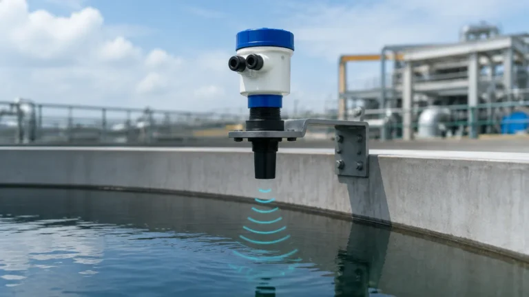
The most common cause of failure in ultrasonic level measurement is improper installation. An ultrasonic level meter manual provides strict geometric requirements to ensure the acoustic pulse is not obstructed or dissipated.
Placement and Orientation
1. Perpendicularity: The transducer face must be installed perfectly parallel to the liquid surface. Even a few degrees of tilt can cause the reflected signal to miss the transducer, resulting in a "Loss of Echo" (LOE) error.
2. Wall Distance: To avoid "false echoes" from the tank walls, the sensor should be placed at a distance from the wall at least 1/6th of the tank's diameter.
3. Inflow Avoidance: Never install the sensor directly above the tank's filling inlet. The turbulence and falling material will scatter the sound waves and create significant noise.
4. Obstructions: Avoid placing the sensor where the beam path might intersect with ladders, heating coils, or agitators. If obstructions are unavoidable, many modern meters allow for "False Echo Suppression" via the manual's software configuration steps.
Mounting in Standpipes
In applications where foam is present or the surface is highly turbulent, a manual may recommend installing the sensor inside a standpipe or stilling well. The pipe acts as a waveguide, focusing the signal and smoothing the liquid surface. However, the manual will specify that the pipe must be smooth and free of burrs or joints that could create interference.
4. Wiring and Electrical Configuration
Modern Ultrasonic Level Meters are available in various electrical configurations. The manual will detail the wiring diagram for the specific model purchased.
* Two-Wire System: The power supply and the 4-20mA output signal share the same pair of wires. This is ideal for standard loop-powered applications.
* Four-Wire System: Power (AC or DC) is supplied separately from the signal output. This is typically used for high-power transducers or when additional relays for pump control are integrated into the meter.
* Digital Communication: Manuals for advanced units will provide register maps for Modbus RTU or instructions for HART protocol integration, allowing for remote diagnostics and configuration.
5. Parameter Setting and Calibration
Once the hardware is installed, the ultrasonic level meter manual guides the user through the software setup. Most industrial meters feature an LCD display with a menu system or a PC-based configuration tool.
Essential Parameters to Configure:
* Tank Height (Full Scale): The distance from the transducer face to the bottom of the tank (4mA point).
* Zero Point: The distance from the transducer face to the lowest expected liquid level (20mA point or vice versa depending on logic).
* Response Speed: This determines how quickly the meter reacts to level changes. For tanks with rapid filling, a "Fast" setting is required; for calm reservoirs, a "Slow" setting helps filter out surface ripples.
* Unit Selection: Choosing between metric (meters, millimeters) or imperial (feet, inches) units.

6. Limitations and Environmental Considerations
While ultrasonic technology is robust, it is not a universal solution. A factual manual will list environmental conditions that can degrade performance:
1. Heavy Foam: Thick, dense foam can absorb the ultrasonic pulse rather than reflecting it. If foam is a constant factor, a radar-based level meter may be more appropriate.
2. Vacuum Conditions: Sound requires a medium (air or gas) to travel. Ultrasonic meters cannot function in a vacuum.
3. High Dust or Vapor: While light dust is manageable, extremely dense dust or heavy steam can attenuate the signal, reducing the effective measuring range.
4. High Pressure: Standard ultrasonic transducers are designed for atmospheric or near-atmospheric pressure. High-pressure environments can alter the speed of sound significantly and may damage the transducer face.
7. Troubleshooting and Maintenance
An engineering-grade ultrasonic level meter manual includes a troubleshooting section to assist in diagnosing common field issues.
* Symptom: Reading jumps to maximum.
* *Cause:* The signal is being lost, and the meter is defaulting to a safety value.
* *Solution:* Check for transducer fouling or check if the beam is hitting an obstruction.
* Symptom: Fixed reading regardless of level.
* *Cause:* The sensor is detecting a fixed obstruction (like a ladder) or the tank wall.
* *Solution:* Perform a "False Echo Map" to tell the sensor to ignore that specific distance.
* Symptom: Inaccurate readings during temperature shifts.
* *Cause:* The internal temperature sensor is being affected by direct sunlight on the housing.
* *Solution:* Install a sunshade over the instrument to ensure the sensor measures the air temperature inside the tank, not the sun-heated housing.
8. Frequently Asked Questions (FAQ)
Q: Can I use an ultrasonic level meter for solids like grain or sand?
A: Yes, but the range is typically reduced by 50% because solids do not reflect sound as efficiently as liquids. The manual will usually provide a "solid-state" adjustment factor.
Q: How do I clean the transducer face?
A: Use a soft cloth and mild detergent. Avoid abrasive materials or harsh chemicals that could damage the matching layer of the transducer. The manual will specify compatible cleaning agents.
Q: Is it possible to shorten the dead zone?
A: The dead zone is a physical property of the transducer's frequency. It cannot be shortened via software. If the level must come closer to the sensor, use a mounting bracket to raise the sensor higher above the tank.
Q: What is the difference between an integrated and a split-type meter?
A: An integrated meter has the sensor and electronics in one housing. A split-type (or remote) meter has a separate sensor connected by a cable to a wall-mounted controller. Split types are useful for hazardous areas or when the sensor is in a hard-to-reach location.
Conclusion
Selecting and maintaining the right level measurement solution requires a disciplined approach to technical documentation. By thoroughly reviewing the ultrasonic level meter manual, engineers can ensure that the chosen Ultrasonic Level Meters are installed correctly, calibrated accurately, and maintained for long-term reliability. Whether managing water treatment facilities, chemical storage, or industrial automation processes, the manual remains the ultimate authority on the instrument's performance and safety limits.