Level Probe
Level Probe
In the landscape of industrial process control, the level probe serves as the critical interface between physical liquid states and digital monitoring systems. Whether managing hazardous chemicals, municipal water supplies, or food-grade ingredients, selecting the correct level probe is fundamental to operational safety, inventory accuracy, and system efficiency. This guide examines the underlying physics of level measurement, the various technologies available, and the practical engineering considerations required for successful deployment.
Fundamental Principles of Level Measurement
Before selecting a level probe, it is essential to understand the physical principles that govern how these instruments detect the surface of a medium. Most industrial probes operate based on pressure, electrical properties, or wave reflection.
Hydrostatic Pressure
The most common principle for liquid level measurement is hydrostatic pressure. According to Pascal’s Law, the pressure at a specific depth within a static liquid is proportional to the height of the liquid column above it. The relationship is expressed by the formula:
P = ρ · g · h
Where *P* is the hydrostatic pressure, *ρ* (rho) is the density of the liquid, *g* is the gravitational constant, and *h* is the height of the liquid. A hydrostatic level probe measures this pressure and converts it into a standardized signal, such as 4-20mA. This method is highly effective for vented tanks and open reservoirs where the liquid density remains constant.
Capacitance and Dielectric Constant
Capacitive level probes treat the tank and the probe as two plates of a capacitor. As the liquid level rises, it displaces air (which has a low dielectric constant) with a liquid that has a different dielectric constant. This change in the medium between the electrodes alters the total capacitance of the circuit. By measuring this change, the instrument can determine the exact level of the product. This principle is particularly useful for both liquids and granulated solids.
Time of Flight (ToF)
Non-contact and guided-wave probes often use Time of Flight technology. This involves emitting a signal—either an ultrasonic sound wave or an electromagnetic radar pulse—and measuring the time it takes for the signal to travel to the surface of the medium and reflect back to the sensor.
* Ultrasonic: Uses sound waves (typically 20 kHz to 200 kHz). The speed of sound is affected by air temperature, necessitating integrated temperature compensation.
* Radar: Uses high-frequency microwave pulses. Since electromagnetic waves are not significantly affected by air temperature or pressure, radar is often preferred for more volatile process environments.
Types of Level Probes and Their Applications
Industrial level probes are categorized by their mounting style and the technology they employ. For a comprehensive overview of available technologies and specific model specifications, engineers should consult the Main Page of professional instrumentation manufacturers.
1. Submersible Level Probes
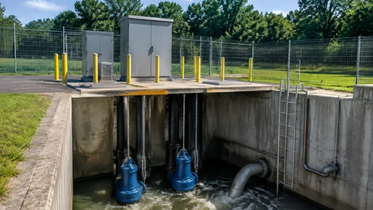
Designed for deep wells, tanks, and wastewater lift stations, these probes are lowered directly into the liquid. They are typically hydrostatic sensors housed in stainless steel or plastic bodies with a reinforced cable that contains a vent tube to compensate for atmospheric pressure changes.
2. Guided Wave Radar (GWR) Probes
GWR probes use a rigid rod or a flexible cable to guide microwave pulses directly to the surface of the medium. This eliminates signal scattering and makes the probe highly effective in narrow tanks or applications with internal obstructions like agitators.
3. Conductive Level Probes
Used primarily for point-level detection (high or low alarms), conductive probes rely on the electrical conductivity of the liquid. When the liquid touches the probe, a circuit is completed between the probe and the tank wall (or a reference probe), triggering a switch. These are cost-effective but limited to conductive liquids like water or acids.
Technical Selection Criteria
Choosing the right level probe requires a detailed analysis of the process environment. The following table provides a comparison of common technologies to assist in the initial selection phase.
Selection Table: Level Measurement Technologies
| Technology | Media Compatibility | Max Temperature | Typical Accuracy | Primary Advantage |
| :— | :— | :— | :— | :— |
| Hydrostatic | Clean liquids, water, oils | Up to 100°C | ±0.25% to ±0.5% | Simple installation, low cost |
| Radar (Non-contact) | Corrosives, slurries, liquids | Up to 250°C+ | ±2 mm to ±5 mm | No contact with media, high precision |
| Guided Wave Radar | Liquids, powders, solids | Up to 400°C | ±2 mm | Works in foam and turbulence |
| Ultrasonic | Wastewater, chemicals | Up to 80°C | ±0.25% of range | Non-contact, low maintenance |
| Capacitive | Acids, alkalis, solids | Up to 200°C | ±0.5% to ±1% | Robust, no moving parts |
Installation Considerations for Engineering Teams
Proper installation is as critical as the selection of the probe itself. Failure to account for tank geometry or environmental factors can lead to signal instability or premature sensor failure.
Positioning and Obstructions
For non-contact probes (Radar and Ultrasonic), the sensor must be mounted away from the tank wall to avoid false reflections (echoes). A general rule is to maintain a distance of at least 200 mm from the wall for every 5 meters of tank height. Additionally, the probe should not be installed directly above the filling inlet, as the falling liquid will disrupt the signal.
Turbulence and Stilling Wells
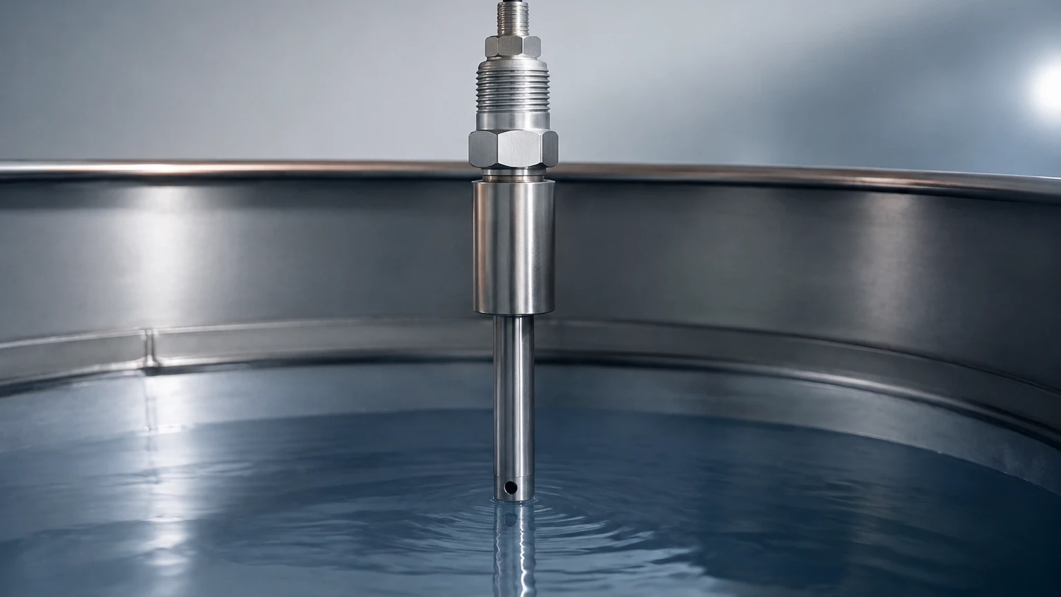
In tanks with heavy agitation or surface turbulence, hydrostatic and ultrasonic probes may provide erratic readings. In these scenarios, a stilling well—a vertical pipe with small holes to allow liquid entry—should be used to create a calm surface for the level probe to measure. This is particularly important for submersible probes to prevent mechanical damage from moving fluid.
Atmospheric Venting
Hydrostatic submersible probes require a vent tube within the cable to ensure the sensor references the local atmospheric pressure. During installation, it is vital to ensure this vent tube is not kinked and is protected by a desiccant filter to prevent moisture from entering the sensor housing, which can cause internal corrosion and drift.
Limitations and Environmental Constraints
No single level probe is universal. Engineers must be aware of the following limitations:
* Density Fluctuations: Hydrostatic probes are sensitive to changes in liquid density. If a tank is used for different fluids at different times, or if the temperature causes significant expansion, the probe must be recalibrated or use a density-compensated algorithm.
* Foam and Vapor: Ultrasonic waves are often absorbed by heavy foam, leading to a "loss of echo" error. In such cases, radar or guided-wave radar is a superior choice as microwaves can penetrate foam and vapors.
* Vacuum Conditions: Ultrasonic sensors cannot function in a vacuum because sound waves require a medium (air) to travel. Radar is the standard choice for vacuum or high-pressure reactors.
* Material Build-up: Capacitive and conductive probes are susceptible to errors if the medium is viscous and leaves a coating on the probe surface. Specialized "coating-rejection" electronics or non-contact sensors should be considered for these applications.
Maintenance and Calibration Protocols
While modern level probes are designed for long-term reliability, a routine maintenance schedule ensures continued accuracy.
1. Visual Inspection: For submersible probes, check the cable jacket for signs of wear or chemical attack. For non-contact sensors, ensure the transducer face or antenna is free from condensation or material buildup.
2. Zero-Point Calibration: Periodically check the "empty" reading of the tank. For hydrostatic sensors, this can be done by lifting the probe out of the liquid to ensure it reads zero pressure.
3. Signal Verification: Use a multimeter to verify that the 4-20mA output corresponds correctly to the physical level measured by a manual dip tape.
Frequently Asked Questions (FAQs)
Q: Can a level probe be used for both liquids and solids?
A: Yes, but the technology must be matched to the material. Radar and capacitive probes are excellent for solids like grain or plastic pellets, whereas hydrostatic probes are strictly for liquids.
Q: What is the maximum depth a submersible level probe can measure?
A: Most standard industrial submersible probes are rated for depths up to 200 meters (approx. 20 bar), though specialized versions exist for deeper borehole monitoring.
Q: How do I handle level measurement in a pressurized tank?
A: For pressurized tanks, a simple hydrostatic probe will not work because it cannot distinguish between liquid pressure and head-space gas pressure. In this case, a differential pressure (DP) transmitter or a radar level probe is required.
Q: Does the color of the liquid affect ultrasonic level probes?
A: No. Ultrasonic sensors rely on sound reflection, which is independent of the optical properties (color or transparency) of the liquid. This makes them superior to some optical sensors in wastewater applications.
Conclusion
Selecting a level probe is a process of balancing technical requirements with budget constraints and environmental realities. By understanding the measurement principles—whether hydrostatic, capacitive, or time-of-flight—and accounting for installation variables like turbulence and tank geometry, engineers can implement a reliable level measurement solution. For those seeking specific hardware configurations or customized OEM/ODM services, visiting the Main Page provides access to a wide range of industrial level measurement instruments tailored for water treatment, chemical processing, and industrial automation.