Fluid Line Technology
Fluid Line Technology
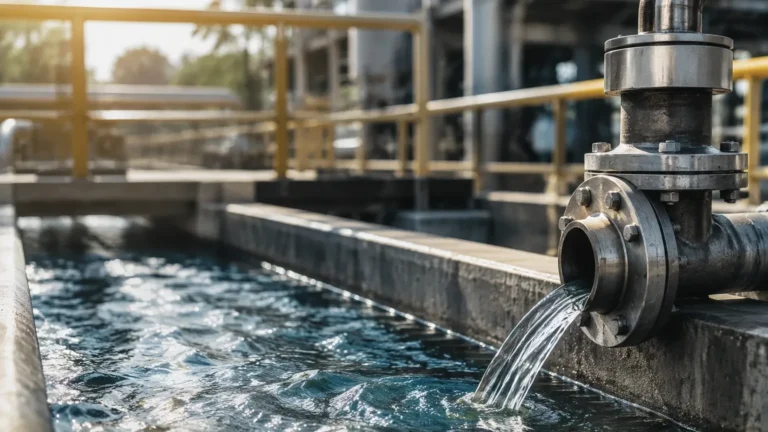
In the landscape of modern industrial automation, fluid line technology represents the critical infrastructure required to transport, control, and monitor liquids and gases within a process facility. Beyond the physical piping and valves, the integration of precise level measurement instrumentation is what transforms a simple fluid line into a managed, intelligent system. For engineers and plant managers, understanding the intersection of fluid dynamics and sensor technology is essential for maintaining process safety, optimizing throughput, and ensuring environmental compliance.
Effective fluid line management relies on the ability to accurately determine the volume or height of media within tanks, vessels, and bypass pipes. This article explores the fundamental principles of level measurement as they apply to fluid line technology, providing a technical framework for selecting and installing the right instrumentation for diverse industrial applications.
Core Principles of Level Measurement in Fluid Systems
Before selecting a sensor for a fluid line application, it is necessary to understand the physics behind the most common measurement technologies. Each method interacts with the fluid and the surrounding environment differently, making certain technologies better suited for specific chemical or physical conditions.
Radar Level Measurement (ToF)
Radar level meters operate on the Time-of-Flight (ToF) principle. The sensor emits high-frequency microwave pulses (typically in the 26GHz or 80GHz range) toward the surface of the liquid. These pulses are reflected by the product surface due to a change in the dielectric constant (εr) between the air and the fluid. The instrument measures the time interval between the emission and the reception of the signal to calculate the distance.
* Non-contact Radar: Ideal for corrosive or high-temperature fluids as the sensor does not touch the media. 80GHz radar, in particular, offers a narrow beam angle, which is advantageous in narrow fluid lines or vessels with internal obstructions.
* Guided Wave Radar (GWR): Uses a physical probe (rod or cable) to guide the microwave signal. This is highly effective for fluids with low dielectric constants or processes involving heavy steam and foam, as the probe concentrates the signal energy.
Ultrasonic Level Sensing
Ultrasonic sensors utilize sound waves rather than electromagnetic waves. The transducer emits an ultrasonic pulse that bounces off the fluid surface and returns to the sensor. The distance is calculated based on the speed of sound in the medium (usually air).
Because the speed of sound is affected by air temperature, most high-quality ultrasonic sensors include an integrated temperature probe to compensate for these changes. This technology is widely used in water treatment and simple chemical storage where the atmosphere is relatively stable.
Hydrostatic Pressure Measurement
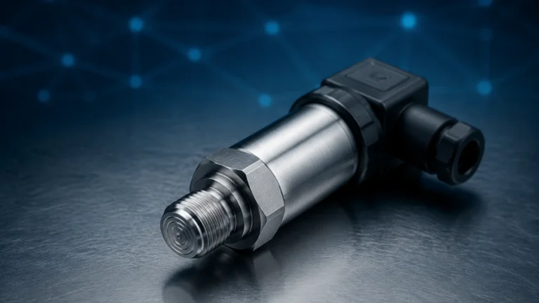
Hydrostatic level transmitters measure the pressure exerted by a liquid column at a specific point. The relationship is defined by the formula: $P = \rho \times g \times h$, where $P$ is pressure, $\rho$ is the fluid density, $g$ is gravity, and $h$ is the height of the liquid. By measuring the pressure at the bottom of a tank or fluid line, the transmitter can determine the level, provided the density remains constant. This is a robust method for deep wells, reservoirs, and vented tanks.
Magnetic Level Gauges
Magnetic gauges are often installed as a bypass to the main fluid line. They consist of a float containing a high-intensity magnet that moves up and down a chamber as the fluid level changes. Outside the chamber, a series of magnetic flags or a transmitter responds to the float's position. This provides both a visual indication and an electronic signal without the need for the sensor to be in direct contact with the process fluid through a seal.
Technological Integration in Fluid Line Systems
Modern fluid line technology is no longer a collection of isolated components. Integration with PLC (Programmable Logic Controller) and SCADA (Supervisory Control and Data Acquisition) systems is standard. Instruments now provide more than just a 4-20mA signal; they offer diagnostic data via HART, Modbus, or Profibus protocols.
Welk, as a professional manufacturer, emphasizes the importance of digital integration. By utilizing advanced signal processing algorithms, modern sensors can filter out "false echoes" caused by agitators or internal piping, ensuring that the fluid line remains operational even in turbulent conditions. This level of intelligence is vital for preventing pump cavitation—a common risk when fluid levels in supply lines drop below a critical threshold.
Selection Criteria for Fluid Line Instrumentation
Choosing the correct instrument requires a detailed analysis of the fluid properties and the physical environment. The following table provides a practical reference for common industrial scenarios.
| Application | Recommended Technology | Key Advantage | Primary Limitation |
| :— | :— | :— | :— |
| Corrosive Chemicals | Non-contact Radar (PTFE faced) | High chemical resistance; no moving parts. | Requires minimum dielectric constant. |
| Wastewater / Effluent | Ultrasonic | Cost-effective; easy to install. | Sensitive to heavy foam and high wind. |
| High-Pressure Steam | Guided Wave Radar | Signal remains stable despite vapor. | Probe can be subject to coating or buildup. |
| Viscous Slurries | Magnetic Level Gauge | Clog-resistant; clear visual backup. | Limited to side-mounting (bypass). |
| Deep Well / Borehole | Hydrostatic (Submersible) | Simple installation in narrow spaces. | Accuracy depends on constant fluid density. |
| Fuel Storage | Magnetostrictive | Extremely high precision (0.1mm). | Sensitive to mechanical vibration. |
Installation Best Practices for Fluid Lines
Even the most advanced sensor will fail if installed incorrectly. When integrating level sensors into fluid line technology, engineers must consider the following factors:
1. Nozzle Dimensions: For radar and ultrasonic sensors, the mounting nozzle should be as short as possible. If the nozzle is too long or narrow, it can create interference (ringing) that masks the true level signal.
2. Dead Zones (Blocking Distance): Every non-contact sensor has a "dead zone" near the face of the transducer where measurement is impossible. Ensure the maximum fluid level never enters this zone to avoid signal loss.
3. Positioning: Sensors should generally be placed at 1/6th of the tank diameter away from the wall to avoid interference from wall reflections, but far enough away from the fluid inlet to avoid turbulence and splashing.
4. Stilling Wells: In applications with high turbulence or heavy foam, installing the sensor inside a stilling well (a vertical pipe) can provide a calm surface for more accurate measurement.

Limitations and Common Risks
While fluid line technology has advanced significantly, certain physical constraints remain. Understanding these limitations is the first step in risk mitigation.
* Dielectric Properties: Radar sensors depend on the reflectivity of the fluid. Non-conductive fluids like oils have low dielectric constants, which result in weaker reflections. In these cases, Guided Wave Radar or high-frequency 80GHz radar is preferred.
* Vapor and Dust: Ultrasonic waves are mechanical and require a medium (air) to travel. Heavy steam, vacuum conditions, or significant dust can attenuate the sound wave, leading to "lost echo" errors. Radar is generally immune to these atmospheric conditions.
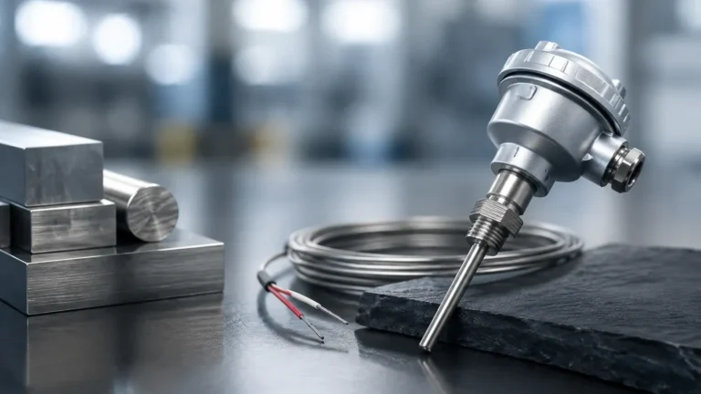
* Density Fluctuations: Hydrostatic sensors assume a constant density. If a process involves mixing different chemicals or significant temperature swings that change the fluid's density, the level reading will drift unless compensated by a secondary pressure sensor or temperature probe.
Maintenance and Long-term Reliability
To ensure the longevity of instrumentation within a fluid line system, a proactive maintenance schedule is recommended. While non-contact sensors require minimal upkeep, they should be inspected periodically for buildup on the transducer face. For wetted sensors, such as hydrostatic probes or magnetic floats, cleaning and inspection for corrosion are necessary to prevent mechanical failure.
Calibration should be verified annually, especially in regulated industries like food and beverage or pharmaceuticals. Most modern instruments allow for field calibration using handheld communicators or laptop software, reducing the need to remove the instrument from the fluid line.
Frequently Asked Questions (FAQ)
Q: Can I use one sensor for different types of fluids?
A: It depends on the technology. Radar and ultrasonic sensors are generally versatile, provided the dielectric constant or sound-reflecting properties are sufficient. However, hydrostatic sensors must be recalibrated if the fluid density changes significantly.
Q: How do I handle foam in my fluid line?
A: Foam is a common challenge. Guided Wave Radar is the most effective solution as the probe guides the signal through the foam to the liquid surface. Alternatively, 80GHz radar can sometimes penetrate light foam, while ultrasonic sensors usually fail in these conditions.
Q: What is the maximum range for these sensors?
A: Submersible hydrostatic sensors can measure up to 200 meters or more. Radar sensors typically reach up to 30 or 70 meters depending on the model, while ultrasonic sensors are generally limited to 15-20 meters.
Q: Is it better to mount a sensor on the top or the side of a vessel?
A: Top-mounting is standard for radar and ultrasonic sensors to provide a clear downward view of the surface. Side-mounting is used for hydrostatic transmitters and magnetic level gauges.
Conclusion
Fluid line technology is a complex field that requires a balance of mechanical engineering and electronic precision. By selecting the appropriate measurement principle—whether it be the electromagnetic precision of radar or the simple reliability of hydrostatic pressure—operators can ensure their systems run safely and efficiently. For detailed technical specifications and to review product options and application support, engineers are encouraged to visit the Main Page of Welk’s industrial instrumentation catalog. Proper selection, combined with rigorous installation standards, forms the backbone of a reliable fluid management strategy.