Liquid Level Controller
Liquid Level Controller
In industrial process automation, the ability to monitor and manage the volume of fluids in tanks, silos, and reservoirs is fundamental to operational efficiency and safety. A liquid level controller serves as the intelligence behind these operations, acting as the bridge between raw measurement data and actionable process control. Whether managing a simple water storage tank or a complex chemical reactor, selecting the right control architecture is essential for preventing overflows, protecting pumps from dry-running, and ensuring consistent product quality.
As a professional manufacturer of industrial level measurement instruments, Welk provides integrated solutions that combine high-precision sensors with robust control logic. This guide explores the technical principles, selection criteria, and installation requirements for modern level control systems used in water treatment, oil and gas, and general industrial automation.
Understanding Measurement Principles and Control Logic
A liquid level controller does not operate in a vacuum; it functions as part of a feedback loop. To understand how to select a controller, one must first understand how the level data is acquired and processed. The system generally consists of three components: the primary sensing element (the sensor), the controller (the logic unit), and the final control element (such as a pump or valve).
1. Signal Acquisition
The controller receives signals from various types of sensors. These signals are typically categorized as:
* Point Level Signals: These are discrete signals (on/off) provided by float switches, tuning fork level switches, or capacitive probes. They indicate whether the liquid has reached a specific height.
* Continuous Level Signals: These provide a constant stream of data representing the exact level. Common outputs include 4-20mA analog loops, 0-10V signals, or digital protocols like RS485 (Modbus RTU) and HART.
2. Processing and Logic
Once the signal is received, the liquid level controller applies programmed logic to determine the output.
* On/Off Control (Hysteresis): This is the most common form of control for pump automation. For example, a controller might turn a pump on when the level reaches 2 meters (6.56 ft) and turn it off when it reaches 8 meters (26.25 ft). This gap, known as hysteresis, prevents the pump from "chattering" or cycling too rapidly.
* Proportional-Integral-Derivative (PID) Control: In more sensitive applications, such as maintaining a constant level in a pressurized vessel while liquid is being drawn out, PID control is used. The controller adjusts a modulating valve to match the inflow with the outflow precisely.
Types of Liquid Level Controllers
Depending on the complexity of the application, controllers are available in several physical and logical configurations.
Panel-Mounted Digital Controllers
These are standalone units installed in a control room or a local electrical cabinet. They feature a digital display showing the current level (often in meters, centimeters, or percentage) and provide multiple relay outputs or analog retransmission. They are highly versatile because they can be paired with almost any sensor type, including radar, ultrasonic, or hydrostatic transmitters.
Integrated Sensor-Controllers
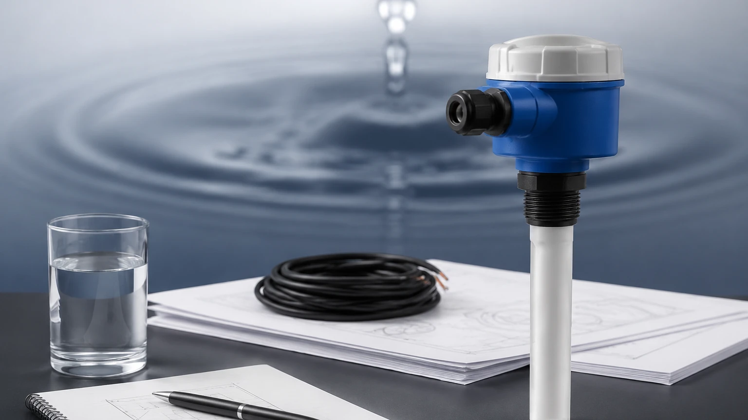
Some modern ultrasonic or radar level meters include built-in relay outputs, effectively acting as a self-contained liquid level controller. This simplifies wiring for basic applications like sump pump control, as the sensor can directly trigger a motor starter without an intermediate control box.
PLC-Based Control
In large-scale industrial plants, level control is often handled by a Programmable Logic Controller (PLC). The level sensor sends a signal to the PLC's input card, and the control logic is handled within the software. This allows for complex interlocks—for example, preventing a tank from filling if a downstream valve is closed.
Key Evaluation Criteria for Selection
Selecting the appropriate control system requires a thorough analysis of the process environment and the physical properties of the liquid. For a detailed look at specific sensor technologies that pair with these controllers, engineers can visit the Main Page to review product options and application support.
1. The Nature of the Medium
* Corrosive Liquids: For acids or bases, non-contact controllers using ultrasonic or radar sensors are preferred to prevent hardware degradation.
* Viscous or Coating Liquids: If the liquid tends to stick to surfaces, tuning fork switches or non-contact radar are better than float-based controllers, which may become stuck.
* Turbulent Surfaces: In tanks with agitators, the controller must have software damping or "filtering" capabilities to ignore momentary level spikes caused by waves.
2. Tank Geometry and Environment
* Depth: For very deep wells or reservoirs (over 20 meters), hydrostatic pressure transmitters paired with a digital controller are often the most cost-effective solution.
* Pressure and Temperature: High-pressure steam boilers require specialized magnetic level gauges with integrated reed switches or magnetostrictive transmitters capable of withstanding extreme conditions.
3. Output Requirements
Determine what the controller needs to trigger. Do you need a simple dry contact for a pump? Or do you need a 4-20mA signal to be sent to a remote SCADA system? Most high-quality controllers offer a combination of both.
Practical Selection Table
The following table provides a general guideline for matching applications with the appropriate level control technology.
| Application | Recommended Sensor Type | Controller Logic | Key Advantage |
| :— | :— | :— | :— |
| Wastewater Sump | Ultrasonic (Non-contact) | On/Off (Duplex Pump) | Low maintenance; no moving parts |
| Chemical Storage Tank | Radar (80GHz) | Continuous + High Alarm | High accuracy; ignores vapors |
| Deep Groundwater Well | Hydrostatic Pressure | Continuous Monitoring | Easy installation in narrow pipes |
| High-Pressure Boiler | Magnetic Level Gauge | Point Level Switches | Visual indication + reliable control |
| Food & Beverage Vat | Capacitive or Tuning Fork | Point Level / Batching | Hygienic design; CIP compatible |
Installation and Engineering Considerations
Proper installation is critical to the reliability of a liquid level controller. Even the most advanced controller will fail if the input signal is noisy or inaccurate.
Positioning the Sensor
* Avoid the Fill Path: Never install a level sensor directly under the liquid inlet. The falling liquid will create turbulence and false readings.
* Dead Zone Awareness: Ultrasonic and radar sensors have a "dead zone" (blocking distance) near the face of the transducer. The controller must be programmed to recognize that the tank is "full" before the liquid enters this zone.
* Stilling Wells: In applications with high foam or extreme turbulence, installing the sensor inside a stilling well (a vertical pipe) can provide a stable surface for measurement.
Wiring and Signal Integrity
* Shielded Cabling: Always use shielded twisted-pair cables for analog signals (4-20mA) to prevent electromagnetic interference (EMI) from nearby motors or variable frequency drives (VFDs).
* Grounding: Ensure the controller and the sensor share a common ground to prevent ground loops, which can cause significant measurement drift.
Common Risks and Limitations
While modern controllers are highly reliable, engineers should be aware of specific environmental factors that can limit performance:
1. Foam: Heavy foam can absorb ultrasonic signals, leading to a "loss of echo." In these cases, radar or hydrostatic sensors are more reliable.
2. Vapor and Vacuum: Ultrasonic waves require a medium (air) to travel. In a vacuum, they cannot function. Similarly, heavy steam can affect the speed of sound, leading to errors. Radar is generally unaffected by these conditions.
3. Build-up: In wastewater or slurry applications, material can build up on the sensor face. Periodic maintenance and cleaning are required unless a non-contact method with a high-power beam is used.
Frequently Asked Questions (FAQ)
Q: Can one controller manage multiple tanks?
A: Yes, multi-channel digital controllers are available that can accept 2, 4, or even 8 sensor inputs simultaneously. This is common in fuel farms or large water treatment facilities.
Q: What is the difference between a level switch and a level controller?
A: A level switch is a simple device that opens or closes a circuit at a specific point. A liquid level controller is a more sophisticated device that can process continuous data, provide displays, and manage complex logic like pump alternation or PID loops.
Q: How do I calibrate a controller for a non-linear tank (e.g., a horizontal cylindrical tank)?
A: Many advanced digital controllers include a "strapping table" or linearization function. You input the tank dimensions, and the controller automatically calculates the volume based on the measured height.
Q: Is wireless level control reliable for industrial use?
A: Wireless protocols like WirelessHART or LoRaWAN are increasingly common for remote tank monitoring. However, for critical safety-related control (like preventing a toxic spill), hardwired connections are still the industry standard due to their deterministic nature.
By carefully matching the sensor technology to the process medium and utilizing a robust liquid level controller, industrial operators can achieve precise automation that reduces waste and enhances safety. For further technical specifications and customized OEM/ODM services, consulting with a specialized manufacturer ensures that the chosen system meets the specific demands of the application.