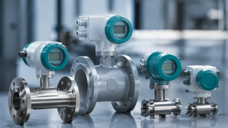
Drum Level Indicator
Drum Level Indicator
In industrial process engineering, the drum level indicator is a critical component for the safe and efficient operation of steam boilers, chemical storage vessels, and liquid accumulation tanks. Whether monitoring the water-steam interface in a high-pressure boiler drum or tracking hazardous chemicals in a storage drum, precise level measurement prevents equipment damage, ensures process continuity, and protects personnel.
Selecting the appropriate drum level indicator requires a deep understanding of the physical properties of the medium, the operating environment, and the specific measurement principles employed by different technologies. This guide explores the engineering fundamentals of drum level measurement, provides selection criteria, and outlines best practices for installation and maintenance.
Measurement Principles for Drum Level Indicators
Before selecting a specific instrument, engineers must evaluate the underlying measurement principle to ensure it aligns with the application's temperature, pressure, and chemical characteristics.
1. Magnetic Level Gauges (Bypass Indicators)
Magnetic level gauges operate on the principle of buoyancy and magnetic coupling. A bypass chamber is mounted to the side of the drum, connected via process flanges. Inside this chamber, a float containing a high-strength permanent magnet moves up and down with the liquid level. Outside the chamber, a column of interlocking magnetic flaps or a follower capsule responds to the float's position.
* Advantages: No glass in contact with the process, high pressure/temperature capability, and clear visual indication from a distance.
* Best For: High-pressure steam drums and hazardous chemical storage.
2. Guided Wave Radar (GWR)
GWR utilizes Time Domain Reflectometry (TDR). A low-energy electromagnetic pulse is sent down a probe (waveguide) immersed in the process medium. When the pulse hits the liquid surface, the change in dielectric constant causes a reflection. The instrument measures the time of flight to calculate the distance.
* Advantages: Not affected by changes in density, pressure, or temperature. Highly accurate even in turbulent conditions.
* Best For: Feedwater drums and process vessels where density fluctuates.
3. Hydrostatic Pressure Measurement
Hydrostatic transmitters measure the pressure exerted by the liquid column at the bottom of the drum. According to the formula $P = \rho gh$ (where $P$ is pressure, $\rho$ is density, $g$ is gravity, and $h$ is height), the level is directly proportional to the pressure if the density remains constant.
* Advantages: Simple installation and cost-effective for vented or atmospheric drums.
* Best For: Open chemical drums and condensate tanks.
4. Ultrasonic Level Sensors
These non-contact sensors emit high-frequency sound waves that reflect off the liquid surface. The sensor calculates the level based on the time it takes for the echo to return.
* Advantages: No moving parts and no contact with the medium, reducing maintenance.
* Limitations: Performance can be degraded by heavy foam, steam, or high-pressure vapors which attenuate sound waves.
5. Non-Contact Radar
Similar to GWR but without a probe, non-contact radar transmits microwave signals through the air. This technology is ideal for highly corrosive environments where contact with the liquid must be avoided.
For a comprehensive overview of available technologies and specific model specifications, engineers can refer to the Main Page for detailed technical documentation.
Practical Selection Table
The following table provides a comparison of common drum level indicator technologies to assist in the initial selection process.
| Technology | Typical Accuracy | Max Temp (Approx.) | Max Pressure (Approx.) | Ideal Application |
| :— | :— | :— | :— | :— |
| Magnetic Gauge | ±5 mm to 10 mm | 450°C (842°F) | 250 bar (3625 psi) | High-pressure boilers, oil/gas separators |
| Guided Wave Radar | ±2 mm to 5 mm | 400°C (752°F) | 400 bar (5800 psi) | Feedwater heaters, chemical process drums |
| Hydrostatic | ±0.1% of span | 120°C (248°F) | N/A (Submersible) | Atmospheric storage, water treatment |
| Ultrasonic | ±0.25% of range | 80°C (176°F) | 3 bar (43 psi) | Wastewater sumps, plastic chemical drums |
| Non-Contact Radar | ±1 mm to 3 mm | 250°C (482°F) | 40 bar (580 psi) | Corrosive chemicals, turbulent liquids |
Installation Considerations
Correct installation is as vital as selecting the right technology. Failure to follow engineering best practices can lead to false readings or premature instrument failure.
Mounting Location
* Avoid Turbulence: Do not install indicators near the drum's inlet or outlet pipes where high-velocity flow or turbulence can cause erratic readings.
* Stilling Wells: For internal radar or ultrasonic sensors in turbulent drums, a stilling well (a perforated pipe) should be used to provide a calm surface for measurement.
* Bypass Chambers: When using magnetic gauges, ensure the bypass chamber is vertically plumb to prevent the float from sticking against the chamber walls.
Process Connections
Standard drum connections usually involve 1/2", 1", or 2" NPT threads or ANSI/DIN flanges. It is essential to ensure that the gaskets and bolting materials are compatible with the process fluid, especially in steam applications where thermal expansion is significant.
Environmental Protection
For outdoor installations, drum level indicators should be equipped with sunshades to prevent electronics from overheating and insulation jackets for bypass chambers to prevent the process fluid from freezing or changing density significantly in cold climates.
Limitations and Common Risks
While modern drum level indicators are highly reliable, certain physical phenomena can introduce measurement errors:
1. Steam Density Compensation: In high-pressure steam boiler drums, the density of both the water and the steam changes with pressure. If using hydrostatic or differential pressure transmitters, the system must include density compensation algorithms to maintain accuracy.
2. Dielectric Constant: Radar-based systems rely on the dielectric constant ($ε_r$) of the liquid. If the $ε_r$ is very low (e.g., certain hydrocarbons), the signal reflection may be weak, requiring specialized high-sensitivity probes.
3. Build-up and Scaling: In chemical drums, material can build up on the float or the radar probe. This increases the weight of the float (causing it to sink lower) or attenuates the radar signal. Regular inspection schedules are necessary for "dirty" processes.
4. "Shrink and Swell": In boiler drums, sudden changes in steam demand can cause the water level to appear to rise (swell) or fall (shrink) due to bubble formation. A single drum level indicator may not be sufficient; often, a three-element control system is required for safety.
Frequently Asked Questions (FAQs)
Q: Can a magnetic drum level indicator be used for interface measurement?
A: Yes. By adjusting the weight of the float to a specific gravity between the two liquids (e.g., oil and water), the float will sink through the top layer and float on the bottom layer, effectively indicating the interface level.
Q: How often should a drum level indicator be calibrated?
A: For critical safety applications like boilers, a quarterly check is recommended. For general chemical storage, an annual calibration is usually sufficient, provided there are no signs of drift or build-up.
Q: Is non-contact radar better than guided wave radar?
A: Not necessarily. Guided wave radar (GWR) is generally better for applications with low dielectric constants or heavy foam, as the probe guides the signal. Non-contact radar is superior for highly corrosive or viscous fluids where you want to avoid any contact with the sensor.
Q: What is the maximum temperature for an ultrasonic drum level indicator?
A: Most ultrasonic sensors are limited to around 80°C (176°F) because the speed of sound is highly dependent on air temperature and vapor composition, which becomes difficult to compensate for at higher temperatures.
Conclusion
A drum level indicator is more than just a visual aid; it is a vital data point for process automation and safety. By understanding the physics behind magnetic, radar, and hydrostatic technologies, engineers can select a solution that balances accuracy with long-term reliability. For those seeking specific hardware recommendations or custom OEM solutions, reviewing the latest product options on the Main Page is the recommended next step in the procurement process.