Flow Line Construction
Flow Line Construction
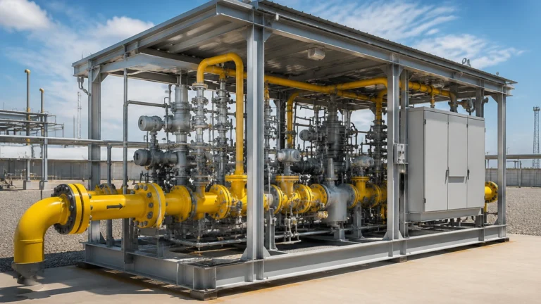
Flow line construction represents a critical phase in the development of industrial infrastructure, particularly within the oil and gas, chemical processing, and water management sectors. A flow line is the pipeline that connects a wellhead to a manifold, a process unit, or a storage facility. Unlike long-distance transmission pipelines, flow lines are often subject to fluctuating pressures, multiphase flow regimes, and varying temperatures, making their design and the integration of monitoring instrumentation a complex engineering challenge.
For engineers and project managers, successful flow line construction requires a balance between mechanical integrity and the implementation of precise measurement technologies. Accurate level and flow monitoring are essential to prevent overpressure events, manage separator efficiency, and ensure the safety of the entire gathering system. This guide explores the technical requirements of flow line construction and the selection of level measurement instruments necessary for operational excellence.
Fundamentals of Flow Line Construction
The construction of a flow line begins with comprehensive route surveying and material selection. Because flow lines often carry raw fluids—which may include a mixture of oil, gas, water, and solids like sand—the internal environment is frequently corrosive or abrasive.
Material Selection and Fabrication
Materials are typically selected based on the fluid chemistry and the operating environment. Common choices include:
- Carbon Steel: Often used for non-corrosive fluids or treated with internal coatings.
- Corrosion-Resistant Alloys (CRA): Such as duplex stainless steel for high-chloride or sour gas (H2S) environments.
- Reinforced Thermoplastics (RTP) or HDPE: Increasing in popularity for water injection lines or low-pressure gathering systems due to their immunity to corrosion.
Fabrication involves stringent welding standards (such as ASME B31.3 or B31.4) and non-destructive testing (NDT) to ensure joint integrity. During the construction phase, the inclusion of "instrumentation tees" or nozzles is vital. These are the points where level sensors and pressure transmitters will be installed to monitor the health of the flow regime.
Measurement Principles for Flow Line Monitoring
Before selecting specific hardware for a flow line project, it is essential to understand the measurement principles that govern industrial level sensors. In flow line applications, sensors are often installed on surge tanks, separators, or knock-out drums integrated into the flow line network.
Radar Level Measurement (Non-Contact)
Radar level meters operate on the Time-of-Flight (ToF) principle. The device emits a high-frequency microwave signal (typically in the 26GHz or 80GHz range) that travels to the liquid surface and reflects back to the sensor. The distance is calculated based on the time interval between transmission and reception.
- Advantage: Since radar waves do not require a physical medium, they are unaffected by vacuum, high pressure, or temperature fluctuations within the flow line.
Ultrasonic Level Measurement
Ultrasonic sensors use sound waves rather than electromagnetic waves. The transducer emits an ultrasonic pulse that reflects off the surface of the medium.
- Advantage: This is a cost-effective solution for atmospheric tanks or open-channel flow monitoring within water treatment flow lines. However, it is sensitive to surface foam and heavy vapors which can attenuate the sound signal.
Hydrostatic Pressure Measurement
This principle relies on the relationship between the height of a liquid column and the pressure it exerts at the base ($P =
ho gh$). A pressure transmitter installed at the bottom of a vessel or a specialized pipe section measures the head pressure, which is then converted into a level reading based on the fluid's density.
- Advantage: Extremely reliable for constant-density fluids and easy to install via threaded or flanged connections.
Selecting Instrumentation for Flow Line Construction
Choosing the right instrument during the flow line construction phase prevents costly retrofits. The following table provides a selection framework based on common process conditions.
| Criteria | Radar (FMCW) | Ultrasonic | Hydrostatic | Magnetic Level Gauge |
| :— | :— | :— | :— | :— |
| Fluid Type | Hydrocarbons, Acids, Slurries | Water, Wastewater | Clean Liquids | Hazardous Chemicals |
| Pressure Range | Up to 160 bar | Atmospheric | Up to 400 bar | Up to 250 bar |
| Temperature | -40°C to +450°C | -40°C to +80°C | -40°C to +120°C | -196°C to +400°C |
| Accuracy | ±1 mm to ±3 mm | ±0.25% of range | ±0.1% to ±0.5% | Visual + ±5 mm |
| Maintenance | Low (No moving parts) | Moderate (Clean sensor face) | Low | Moderate (Float cleaning) |
When evaluating these options, engineers should Review product options and application support to ensure compatibility with the specific pipe schedules and flange ratings used in their flow line construction project.
Installation Considerations and Best Practices
Proper installation is as critical as the construction of the pipe itself. Even the most advanced radar level meter will fail to provide accurate data if installed incorrectly.
1. Nozzle Geometry: For radar and ultrasonic sensors, the height and diameter of the mounting nozzle must be considered. If a nozzle is too long or narrow, it can create internal reflections (ringing) that interfere with the actual level signal.
2. Obstruction Avoidance: Sensors should be positioned away from internal pipe structures, such as heating coils, ladders, or agitators. In flow line surge tanks, the inlet flow should not be directly beneath the sensor to avoid turbulence-induced errors.
3. Stilled Pipes and Bypass Chambers: In applications involving heavy foam or extreme turbulence, installing the level sensor within a stilling well or an external bypass chamber is recommended. This provides a calm surface for the measurement signal.
4. Environmental Protection: Flow lines are often located in remote, harsh environments. Instrumentation must have appropriate Ingress Protection (IP66/67 or higher) and hazardous area certifications (ATEX/IECEx) if flammable gases are present.

Common Risks in Flow Line Construction
Flow line projects face several technical and environmental risks that can compromise both the structure and the monitoring accuracy:
- Paraffin and Scale Buildup: In oil flow lines, wax (paraffin) can deposit on the inner walls and on sensor faces. This can lead to "frozen" readings in hydrostatic sensors or signal loss in ultrasonic devices. Radar is generally more resistant but may still require periodic cleaning of the antenna.
- Slug Flow: Multiphase flow lines often experience "slugging," where large pockets of gas and liquid alternate. This creates massive mechanical vibration and rapid level fluctuations that can damage poorly secured instrumentation.
- Erosion: High-velocity particles (sand) can erode the protective diaphragms of pressure transmitters or the internal lining of the flow line.
- Thermal Expansion: Long sections of flow line will expand and contract. Without proper expansion loops and flexible instrument connections, the stress can shear off sensor nozzles.
Project Confirmation Checklist
Before proceeding with the procurement of level measurement solutions for flow line construction, the following data points must be confirmed by the engineering team:
- [ ] Fluid Characteristics: Is the fluid corrosive, viscous, or prone to foaming? What is the specific gravity (density)?
- [ ] Process Limits: What are the absolute maximum and minimum operating pressures and temperatures?
- [ ] Physical Constraints: What is the available mounting space? Are there height restrictions for the sensor head?
- [ ] Communication Protocol: Does the facility require 4-20mA HART, Modbus RTU, or Foundation Fieldbus integration?
- [ ] Regulatory Compliance: Does the project require SIL (Safety Integrity Level) rated components for overfill prevention?
Conclusion
Flow line construction is more than just laying pipe; it is the creation of a controlled environment for fluid transport. The integration of high-precision level measurement instruments—such as those found on the Welk Main Page—is essential for the longevity and safety of these systems. By understanding the underlying physics of radar, ultrasonic, and hydrostatic measurement, and by following strict installation protocols, operators can ensure that their flow lines perform reliably under the most demanding industrial conditions.
Frequently Asked Questions (FAQ)
Q: Can radar level meters work in high-pressure flow lines?
A: Yes, specialized radar meters with high-pressure flange interfaces and ceramic or PTFE seals can operate in environments exceeding 100 bar (1450 psi).
Q: How do I handle level measurement in a flow line with heavy foam?
A: High-frequency (80GHz) radar is often effective as it can penetrate thin foam, but for thick, dense foam, a guided wave radar (GWR) or a displacement-type sensor in a bypass chamber is usually the more reliable choice.
Q: Is it necessary to insulate level sensors in cold climates?
A: While the electronics are usually rated for low temperatures, the process fluid in the nozzle might freeze or thicken. Heat tracing or insulation on the mounting nozzle and bypass chamber is often necessary to maintain fluid mobility for accurate measurement.