Liquid Level Switch Float
Liquid Level Switch Float
In the landscape of industrial process control, the liquid level switch float remains one of the most reliable and widely implemented technologies for point-level detection. Despite the emergence of complex electronic sensors, the fundamental physics of buoyancy combined with magnetic actuation offers a robust solution for water treatment, chemical processing, and oil and gas industries. This guide provides a technical overview of float-based level switches, their operating principles, selection criteria, and practical installation considerations for engineering professionals.
Principles of Float-Based Level Detection
The operation of a liquid level switch float is governed by Archimedes' Principle, which states that any object, wholly or partially immersed in a fluid, is buoyed up by a force equal to the weight of the fluid displaced by the object. In a level switch context, this buoyancy force is used to move a mechanical or magnetic component to trigger an electrical signal.
The Magnetic Reed Switch Mechanism
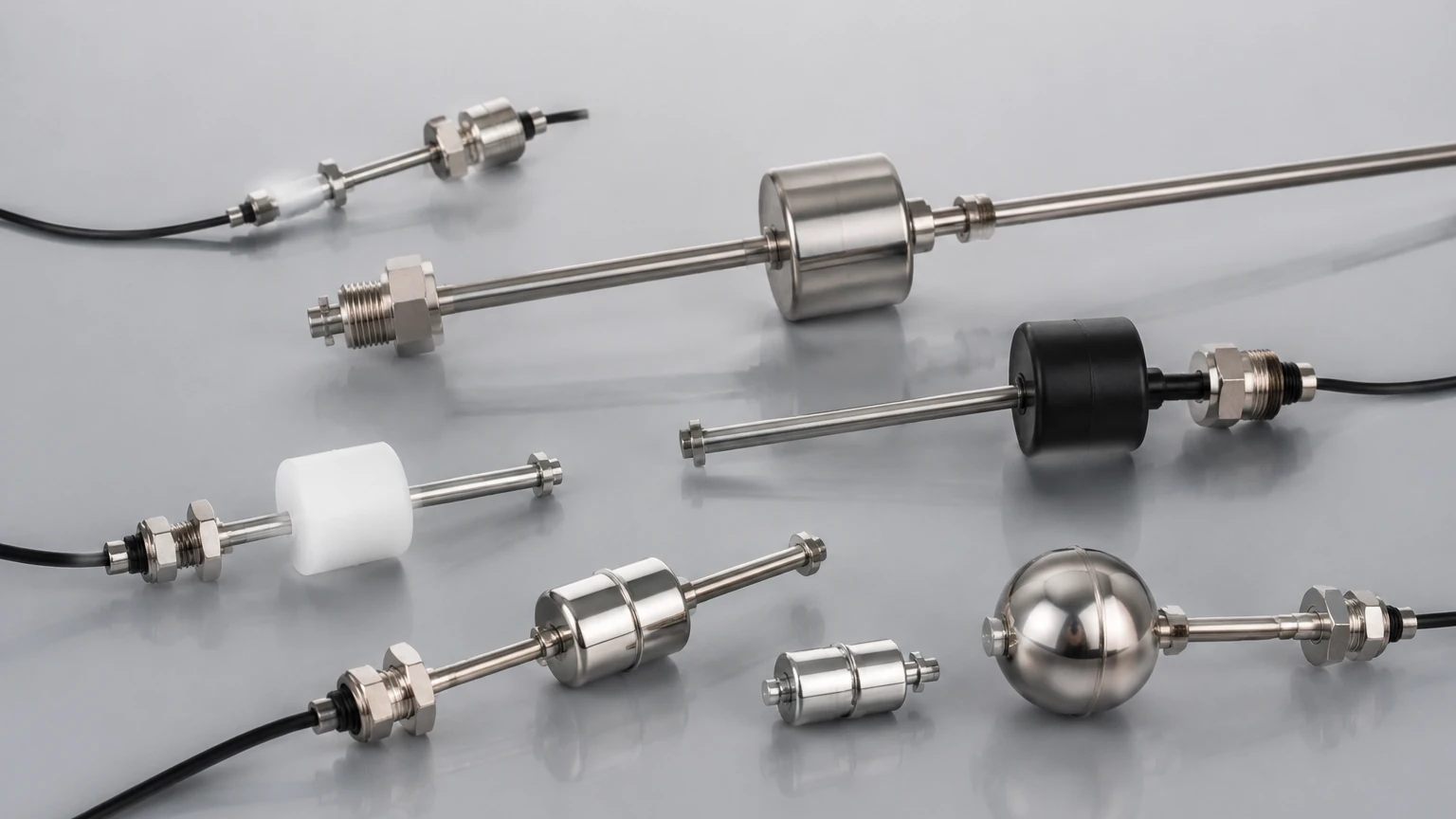
Most modern industrial float switches, such as those manufactured by Welk, utilize a magnetic reed switch mechanism. The assembly typically consists of a hollow float containing a permanent magnet and a stationary stem containing a hermetically sealed reed switch. As the liquid level rises, the float slides up the stem. When the float's internal magnet reaches the position of the reed switch, the magnetic field causes the switch contacts to close (or open, depending on the configuration).
This design offers several advantages in B2B applications:
- Isolation: The electrical components are completely sealed within the stem, protecting them from the process media.
- Durability: Because there is no direct mechanical linkage between the float and the switch, wear and tear are significantly reduced.
- Versatility: The switch can be configured as Normally Open (NO) or Normally Closed (NC) simply by inverting the float on the stem.
Common Types of Liquid Level Switch Float Designs
Selecting the correct geometry and mounting style is critical for ensuring long-term reliability in industrial automation. Float switches are generally categorized by their mounting orientation and the number of detection points.
1. Vertical Float Switches
Vertical switches are mounted through the top or bottom of a tank. They are ideal for deep vessels where multiple level points (e.g., high-high, high, low, and low-low alarms) need to be monitored using a single entry point. The stem can be customized to lengths exceeding 2,000 mm (approx. 78 inches), accommodating various tank depths.
2. Horizontal (Side-Mounted) Float Switches
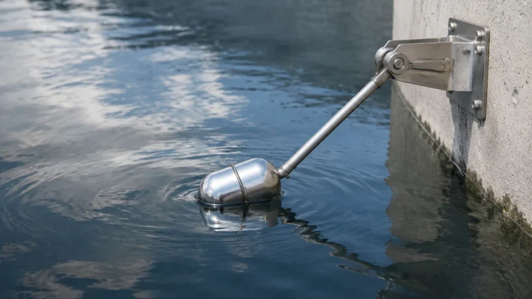
Side-mounted switches are used when the top of the tank is inaccessible or occupied by other equipment. These units typically feature a hinged float that moves in an arc. When the liquid level reaches the float, it pivots, moving a magnet toward a reed switch located in the mounting hex. These are common in small tanks or for simple high/low overflow protection.
3. Cable Float Switches
Used extensively in water treatment and sewage sumps, cable float switches consist of a large, buoyant body attached to a flexible cable. Inside the float is a microswitch and a rolling ball. As the float tilts with the rising water, the ball rolls to actuate the switch. These are preferred for non-critical applications involving turbulent or dirty liquids where a rigid stem might become fouled.
Technical Selection Criteria for Industrial Applications
Engineering the right solution requires a detailed understanding of the process environment. When reviewing product options and application support at the Main Page, consider the following parameters:
Material Compatibility
The material of the float and stem must withstand the chemical properties of the liquid.
- Stainless Steel (304 or 316L): The standard for high-pressure (up to 30 bar / 435 PSI) and high-temperature (up to 200°C / 392°F) applications. It is suitable for food processing, oil, and various chemicals.
- Polypropylene (PP): A cost-effective choice for acidic or alkaline solutions at lower temperatures (up to 80°C / 176°F).
- PVDF/PTFE: Reserved for highly aggressive corrosive environments where even stainless steel might fail.
Specific Gravity
The float must be lighter than the liquid it is intended to measure. Industrial floats are typically rated for a minimum specific gravity (SG). For example, a float designed for water (SG 1.0) may not function correctly in light oils or fuels with an SG of 0.7 unless specifically engineered with a lower density.
Selection Table: Material and Application Comparison
| Material | Max Temperature | Max Pressure | Typical Application |
| :— | :— | :— | :— |
| Polypropylene (PP) | 80°C (176°F) | 5 bar (72 PSI) | Water tanks, mild acids, plating baths |
| Stainless Steel 316 | 120°C – 200°C | 30 bar (435 PSI) | Oil, hydraulic fluid, high-temp water |
| NBR (Buna-N) | 100°C (212°F) | 10 bar (145 PSI) | Fuel tanks, lubricants |
| PVDF | 110°C (230°F) | 10 bar (145 PSI) | Concentrated chemicals, high purity |
Installation Best Practices and Configuration
To ensure the accuracy of a liquid level switch float, proper installation is mandatory. Mechanical interference and fluid dynamics are the most common causes of failure.
Mounting and Positioning
1. Avoid Turbulence: Do not install the switch directly near a liquid inlet or an agitator. The resulting turbulence can cause "chatter"—the rapid opening and closing of the switch—which can damage pumps or control systems.
2. Stilling Wells: In tanks with significant agitation, install the float switch inside a stilling well (a vertical pipe with vent holes). This provides a calm environment for the float to move accurately.
3. Vertical Alignment: Vertical switches should be mounted within 30 degrees of true vertical. Excessive tilting can increase friction between the float and the stem, leading to sticking.
Electrical Considerations
Float switches are generally low-power devices. While they can trigger a small relay, they should never be used to directly power a high-current pump motor. Always use a control relay or a PLC input to handle the load. For hazardous areas, ensure the switch is used in conjunction with an intrinsically safe barrier.
Limitations and Operational Constraints
While the liquid level switch float is highly versatile, it is not a "one-size-fits-all" solution. Engineers must be aware of the following limitations:
- Viscosity and Coating: Highly viscous liquids (like heavy syrups or crude oil) can impede the movement of the float. Similarly, liquids that crystallize or leave heavy deposits can cause the float to seize on the stem.
- Magnetic Interference: Since these switches rely on internal magnets, the presence of ferrous particles in the liquid can be problematic. Iron filings can accumulate on the float's magnet, eventually weighing it down or causing it to stick. In such cases, magnetic traps or non-contact ultrasonic sensors may be required.
- Mechanical Wear: Although the reed switch is rated for millions of cycles, the float itself is a moving part. In applications with constant, rapid level fluctuations, mechanical fatigue of the hinge or friction on the stem can occur over several years.
Frequently Asked Questions (FAQs)
Q: Can I change a float switch from Normally Open to Normally Closed?
A: For most vertical magnetic float switches, yes. You can remove the retaining clip, flip the float 180 degrees, and replace it. This reverses the polarity of the magnet relative to the switch.
Q: What is the minimum specific gravity a float can handle?
A: Standard industrial floats usually require an SG of 0.7 or higher. However, specialized ultra-light floats are available for liquids with an SG as low as 0.45.
Q: How do I test a float switch without filling the tank?
A: You can manually slide the float up and down the stem while checking the continuity across the lead wires with a multimeter. For side-mounted switches, simply pivot the arm manually.
Q: Why did my reed switch fail after only a few cycles?
A: This is often caused by an inductive load (like a solenoid valve or motor) creating a voltage spike when the switch opens. This can weld the reed contacts together. Always use a snubber circuit or a protective relay.
Conclusion
The liquid level switch float remains a cornerstone of industrial level control due to its simplicity and high reliability. By understanding the chemical compatibility of materials like 316 stainless steel and polypropylene, and by accounting for specific gravity and installation dynamics, engineers can implement cost-effective solutions for even the most demanding environments. For customized OEM/ODM services or high-accuracy radar and ultrasonic alternatives, Welk provides a comprehensive range of instruments to meet modern automation needs.