Metallic Level Sensors
Metallic Level Sensors
In the demanding landscape of industrial process control, the term "metallic level sensors" refers to a broad category of instrumentation where the primary construction materials—specifically the wetted parts and housing—are composed of alloys such as stainless steel, Hastelloy, or Monel. These instruments are engineered to withstand the rigors of high-pressure, high-temperature, and chemically aggressive environments found in sectors like oil and gas, chemical processing, and heavy manufacturing. Choosing the correct sensor requires a deep understanding of both the physical properties of the metal and the underlying measurement physics.
Measurement Principles of Metallic Level Sensors
Before selecting a specific instrument, engineers must evaluate the measurement principle that best suits the medium and the vessel geometry. Metallic level sensors typically utilize one of the following four principles.
1. Radar Level Measurement (Non-contact and Guided)
Radar sensors utilize electromagnetic waves to determine the distance to the surface of a liquid or solid. In non-contact radar, a metallic antenna (often a horn or parabolic shape) emits a high-frequency signal. The time-of-flight between emission and the reception of the reflected signal is used to calculate the level.
Guided Wave Radar (GWR) uses a metallic probe—such as a single rod, twin rod, or coaxial cable—to direct the signal. This is particularly effective in low dielectric media or narrow tanks where internal obstructions might interfere with a free-space signal. The metallic construction of the probe allows it to survive extreme mechanical stress and thermal expansion.
2. Hydrostatic Pressure Measurement
Hydrostatic sensors measure the pressure exerted by a liquid column at a specific point. The principle is based on the formula: $P = \rho \times g \times h$, where $P$ is pressure, $\rho$ is the density of the liquid, $g$ is gravity, and $h$ is the height of the liquid.
In these sensors, a metallic diaphragm (usually 316L stainless steel or Hastelloy) is in direct contact with the process. The deformation of this diaphragm is converted into an electrical signal. Because the sensor relies on the physical integrity of the metal diaphragm, material selection is critical to prevent fatigue or chemical pitting.
3. Magnetic Level Gauges and Switches
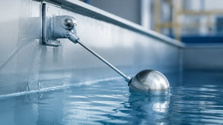
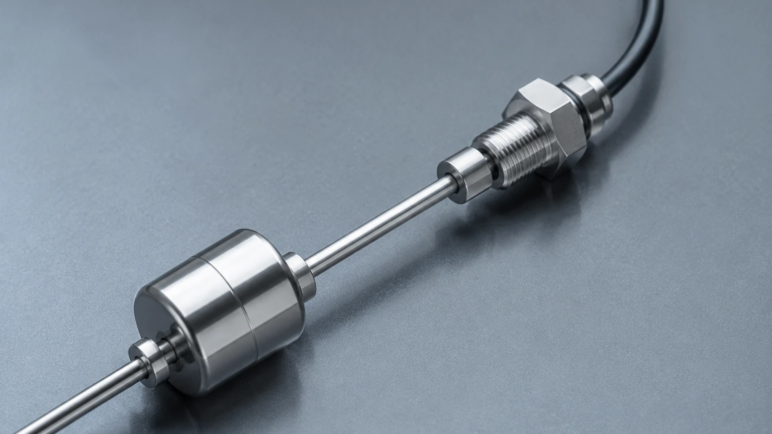
Magnetic level sensors rely on the principle of buoyancy and magnetic coupling. A metallic float containing a permanent magnet moves up and down a bypass chamber or a guide tube. As the float moves, it interacts with external indicators or reed switches. The use of metallic chambers (often 316L or 304 stainless steel) allows these sensors to operate in high-pressure steam applications where glass-based sight gauges would be unsafe.
4. Ultrasonic Level Sensing
While many ultrasonic sensors are plastic, industrial-grade metallic level sensors use metallic transducers to transmit sound waves. These are preferred in hygiene-sensitive industries like food and beverage or pharmaceuticals, where the sensor must withstand Clean-in-Place (CIP) cycles involving high-temperature caustic washes.
Key Material Considerations for Metallic Sensors
The performance of metallic level sensors is intrinsically linked to the metallurgy of the wetted parts. Standard options include:
* 304 Stainless Steel: Suitable for basic water treatment and non-corrosive industrial liquids. It offers good mechanical strength but limited resistance to chlorides.
* 316L Stainless Steel: The industry standard for most chemical and oil applications. The "L" denotes low carbon content, which improves weldability and resistance to intergranular corrosion.
* Hastelloy C-276: An exotic alloy used for extremely aggressive media, such as sulfuric acid or chlorine-based compounds, where stainless steel would fail within weeks.
* Titanium: Used primarily in seawater applications or specialized chemical processes where high strength-to-weight ratios and specific corrosion resistance are required.
Practical Selection Table
The following table provides a comparison of common metallic level sensor technologies to aid in the initial selection process.
| Technology | Accuracy | Max Temperature | Max Pressure | Typical Media |
| :— | :— | :— | :— | :— |
| Non-contact Radar | ±2 mm | Up to +450°C | Up to 16 MPa | Hydrocarbons, chemicals, solids |
| Guided Wave Radar | ±3 mm | Up to +400°C | Up to 40 MPa | Liquefied gases, bitumen, acids |
| Hydrostatic | ±0.1% FS | Up to +120°C | Up to 60 MPa | Water, fuel, wastewater |
| Magnetic Gauge | ±5 mm | Up to +400°C | Up to 32 MPa | Boiler water, oil, toxic chemicals |
| Ultrasonic | ±0.25% FS | Up to +80°C | Up to 0.3 MPa | Water, juices, slurries |
Installation Considerations for Metallic Instruments
Proper installation is as critical as sensor selection. When working with metallic level sensors, engineers should prioritize the following factors:
Mounting and Nozzle Design
For radar-based metallic level sensors, the nozzle height and diameter are vital. If the nozzle is too long or narrow, the metallic walls of the nozzle can create "ringing" or parasitic reflections that mask the actual level signal. Ideally, the antenna should extend slightly beyond the nozzle bottom into the tank.
Grounding and Conductivity
In applications involving flammable liquids or explosive dusts (ATEX/Ex zones), the metallic housing of the sensor must be properly grounded to the vessel. This prevents the buildup of static electricity, which could lead to a discharge and subsequent ignition. Using metallic flanges with appropriate conductive gaskets ensures electrical continuity.
Thermal Expansion
In high-temperature applications, metallic probes (especially in Guided Wave Radar) will undergo thermal expansion. For a 10-meter stainless steel probe, a temperature increase of 200°C can result in several centimeters of expansion. The installation must allow for this movement, often by using a weighted end-of-probe spacer rather than a rigid bottom fix.
Dead Zones (Blocking Distance)
Every sensor has a "dead zone" near the mounting point where measurement is not possible. For metallic level sensors using ultrasonic or radar technology, this is typically between 100 mm and 500 mm. If the tank is frequently filled to the brim, a nozzle extension or a different mounting location may be required to keep the maximum level outside of this dead zone.
Limitations and Common Risks
Despite their durability, metallic level sensors are not universal solutions. Engineers must be aware of specific risks:
1. Chemical Incompatibility: Even high-grade stainless steel can succumb to stress corrosion cracking in the presence of halides or high-temperature chlorides. Always consult a chemical compatibility chart before specifying the alloy.
2. Build-up and Coating: In viscous or crystallizing media, material can accumulate on the metallic probe or diaphragm. While radar can often "see through" thin coatings, heavy build-up on a hydrostatic diaphragm will cause significant measurement drift.
3. Dielectric Constant Limits: Radar-based metallic level sensors require a minimum dielectric constant ($εr$) to reflect a signal. If the medium has a very low $εr$ (like certain dry powders or pure hydrocarbons), a guided wave radar with a coaxial metallic probe is often necessary to concentrate the signal.
4. Turbulence and Foam: Heavy foam can absorb radar and ultrasonic signals. In these cases, a metallic bypass chamber or a stilling well is recommended to provide a calm surface for the sensor to measure.
Frequently Asked Questions (FAQ)
Q: Can I use a stainless steel sensor for hydrochloric acid (HCl)?
A: Generally, no. Standard 316L stainless steel has poor resistance to HCl. For such applications, you should look for metallic level sensors with Tantalum wetted parts or specialized PTFE/PFA coatings over the metallic substrate.
Q: How do I calibrate a hydrostatic metallic level sensor?
A: Calibration is usually done by comparing the sensor's output (e.g., 4-20mA) to a known level or by using a pressure calibrator. Since the sensor measures pressure, you must ensure the density setting in the transmitter matches the actual density of the liquid in the tank.
Q: Why choose a metallic housing over plastic?
A: Metallic housings offer superior shielding against Electromagnetic Interference (EMI) and are much more resistant to UV degradation and mechanical impact in outdoor or heavy industrial environments.
Conclusion and Next Steps
Selecting the right metallic level sensors involves balancing the physical properties of the media with the operational requirements of the plant. Whether you require the precision of 80GHz radar or the rugged simplicity of a magnetic float gauge, the material integrity of the sensor remains the first line of defense against process failure. For a comprehensive overview of available technologies and to find a solution tailored to your specific industrial application, you can Review product options and application support on our Main Page.
Before finalizing a purchase, project teams should confirm the following:
* The maximum operating pressure and temperature (including cleaning cycles).
* The specific chemical composition and concentration of the media.
* The presence of agitation, foam, or internal tank obstructions.
* Required local certifications (e.g., SIL, ATEX, FM, or FDA compliance).