Evapco Cooling Tower Level Sensor
Evapco Cooling Tower Level Sensor
In industrial heat rejection systems, maintaining the precise water level within a cooling tower basin is critical for operational efficiency, equipment longevity, and safety. For facilities utilizing Evapco equipment, the evapco cooling tower level sensor serves as the primary interface between the physical water volume and the automated control system. This guide provides a technical overview of the measurement principles, selection criteria, and installation best practices for level instrumentation in cooling tower applications.
Effective level management prevents two primary failure states: basin overflow, which wastes water and expensive treatment chemicals, and low-water conditions, which can lead to pump cavitation, air entrainment, and catastrophic failure of heat transfer surfaces. Understanding the underlying technology of these sensors is the first step in optimizing cooling tower performance.
Measurement Principles for Cooling Tower Level Control
Before selecting a specific evapco cooling tower level sensor or an aftermarket replacement, engineers must understand the physical principles used to detect water levels. Cooling towers present a challenging environment characterized by turbulence, humidity, temperature fluctuations, and chemical additives.
Conductivity (Electrode) Sensing
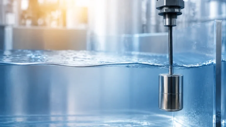
Conductivity sensors are perhaps the most common technology found in standard cooling tower configurations. These systems utilize stainless steel probes of varying lengths suspended into the basin. When water touches a probe, an electrical circuit is completed between the probe and a ground reference.
This technology is discrete rather than continuous, typically providing signals for "High Level," "Low Level," "Make-up On," and "Make-up Off." While highly reliable and cost-effective, conductivity probes are susceptible to scale buildup (calcium carbonate) and fouling, which can insulate the probes and lead to false readings.
Ultrasonic Level Measurement
Ultrasonic sensors are non-contact devices that emit high-frequency sound pulses. The sensor measures the time it takes for the pulse to travel to the water surface and reflect back. Because they do not touch the process media, they are immune to the corrosive effects of water treatment chemicals.
However, ultrasonic sensors can struggle in cooling towers where heavy steam or foam is present. Since sound travels through air, significant changes in air temperature or density within the tower casing can affect the accuracy of the time-of-flight calculation.
Radar (Microwave) Level Measurement
Radar sensors, particularly high-frequency 80GHz units, represent the premium tier of cooling tower level measurement. Like ultrasonic sensors, they are non-contact, but they use electromagnetic waves instead of sound. Radar is unaffected by steam, vacuum, pressure, or air temperature fluctuations. This makes them ideal for towers operating in extreme climates or high-load industrial processes where heavy vapor plumes are constant. For a deeper look at high-precision radar options, you may consult our Main Page.
Hydrostatic Pressure Sensing
Hydrostatic transmitters measure the pressure exerted by the column of water in the basin. Since pressure is directly proportional to the height of the liquid (based on the formula $P = \rho gh$), these sensors provide a continuous 4-20mA signal representing the exact level. These are typically mounted at the bottom of the basin or via a submerged probe. They are excellent for providing high-resolution data but must be compensated for changes in liquid density if the concentration of dissolved solids varies significantly.
Technical Comparison of Sensor Technologies
Choosing the right evapco cooling tower level sensor requires balancing initial cost against maintenance requirements and the need for continuous data.
| Technology | Measurement Type | Accuracy | Maintenance Level | Best For |
| :— | :— | :— | :— | :— |
| Conductivity Probes | Point (Discrete) | Moderate | High (Cleaning) | Standard OEM replacements |
| Ultrasonic | Continuous | High | Low | General purpose, non-contact |
| Radar (FMCW) | Continuous | Very High | Very Low | High-steam or turbulent basins |
| Hydrostatic | Continuous | High | Moderate | Deep basins or outdoor tanks |
| Float Switches | Point (Discrete) | Low | Moderate | Simple high/low alarms |
Integration with Evapco Control Systems
Most modern Evapco units utilize an Electronic Water Level Control (EWLC) system. This system is designed to replace traditional mechanical float valves, which are prone to sticking and leaking. The evapco cooling tower level sensor in these systems usually consists of a multi-probe conductivity set housed in an external stilling chamber or mounted directly in the basin.
The Role of the Stilling Well
The water surface in a cooling tower basin is rarely still. The downward flow of water from the fill media and the suction from the pumps create significant turbulence and surface ripples. To prevent "chatter"—the rapid cycling of make-up valves—sensors are often installed inside a stilling well. This is a vertical pipe (typically 50mm to 150mm / 2" to 6" in diameter) that dampens surface fluctuations, providing a stable environment for the sensor to provide an accurate reading.
Solenoid Valve Coordination
The level sensor signal is processed by a controller that manages the make-up water solenoid valve. A well-configured system will include a "deadband" or hysteresis. For example, the sensor may trigger the make-up valve to open when the level drops to 100mm (4 inches) and close it only when it reaches 150mm (6 inches). This prevents excessive wear on the valve and plumbing.
Installation Considerations and Best Practices
Proper installation of an evapco cooling tower level sensor is as important as the technology itself. Failure to follow engineering guidelines often leads to premature sensor failure or erratic control.
1. Positioning: Sensors should be located away from the immediate vicinity of the make-up water inlet and the pump suction. The inlet creates localized turbulence, while the suction can create a vortex that lowers the local water level relative to the rest of the basin.
2. Environmental Protection: While most sensors are rated IP65 or IP67, the wiring connections in a cooling tower environment are subject to constant moisture. Using liquid-tight conduits and ensuring drip loops are present in the wiring will prevent moisture from wicking into the sensor housing.
3. Grounding: For conductivity-based sensors, proper grounding of the basin or the common probe is essential. Without a solid ground reference, the small electrical currents used for sensing can be lost, leading to intermittent signal loss.
4. Scaling and Fouling: In systems with high cycles of concentration, mineral scale will accumulate on any submerged surface. If using conductivity probes, they should be installed in a location that is easily accessible for quarterly cleaning with a mild descaling solution.
Limitations and Common Risks
While automated level sensing is superior to mechanical floats, it is not without risks. Engineers should be aware of the following limitations:
* Chemical Interference: Certain water treatment chemicals, particularly film-forming amines or high concentrations of surfactants, can affect the conductivity of the water or create foam that interferes with ultrasonic signals.
* Vibration: Cooling towers are high-vibration environments due to large fans and motors. Sensors must be mounted securely to rigid structural members to prevent mechanical fatigue of the sensor housing or mounting threads.
* Freezing: In cold climates, water in stilling wells or external sensing lines can freeze even if the main basin is heated. Heat tracing or ensuring the sensor is located in a "warm" zone of the basin is necessary for year-round operation.
Frequently Asked Questions (FAQ)
Q: How often should I calibrate my cooling tower level sensor?
A: For continuous sensors like radar or hydrostatic transmitters, an annual calibration check is recommended. Conductivity probes do not require calibration but should be inspected every 3–6 months for scale buildup.
Q: Can I replace a mechanical float valve with an electronic sensor?
A: Yes. This is a common upgrade. You will need the sensor, a controller (to process the signal), and a solenoid valve for the make-up water line. This setup significantly reduces water waste and maintenance.
Q: Why is my level sensor showing a full basin when it is actually empty?
A: This is a common symptom of "bridging" in conductivity probes, where a layer of scale or moisture creates a conductive path between the probe and the housing, mimicking the presence of water. Cleaning the probes and insulators usually resolves this.
Q: Is radar overkill for a standard cooling tower?
A: While more expensive, radar is often the most cost-effective long-term solution for critical process cooling where downtime is expensive. The lack of maintenance and immunity to steam often offset the higher initial purchase price.
Conclusion
Selecting the appropriate evapco cooling tower level sensor requires a thorough understanding of the specific tower's operating conditions. Whether opting for the simplicity of conductivity probes or the high-precision, non-contact reliability of radar, the goal remains the same: maintaining a stable water level to ensure the cooling system operates at peak thermal efficiency. For further technical specifications and to explore a wide range of industrial level measurement instruments, please visit our Main Page. By following the measurement principles and installation guidelines outlined here, facility managers can significantly reduce water waste and protect their cooling infrastructure from avoidable damage.