Line Sensing
Line Sensing
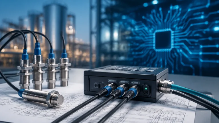
In the field of industrial process automation, line sensing refers to the continuous measurement of material levels along a vertical or horizontal axis. Unlike point level detection, which only identifies whether a substance has reached a specific threshold, line sensing provides a real-time, graduated data stream of the liquid or solid interface throughout the entire height of a vessel. This capability is critical for inventory management, process optimization, and safety in sectors ranging from chemical processing to water treatment.
Selecting the appropriate technology for line sensing requires a deep understanding of the physical principles governing different sensors. Engineers must evaluate the dielectric properties of the media, the presence of turbulence, and the physical constraints of the tank. This guide examines the primary technologies used for continuous line sensing, their operational mechanics, and practical selection criteria for industrial applications.
Measurement Principles of Line Sensing Technologies
To achieve reliable continuous measurement, various physical phenomena are leveraged to track the interface between two phases (e.g., liquid/gas or liquid/liquid). The most common methods include electromagnetic wave reflection, electrical capacitance, and hydrostatic pressure.
Guided Wave Radar (GWR)
Guided Wave Radar is a high-performance line sensing technology based on Time Domain Reflectometry (TDR). In this method, a low-energy microwave pulse is sent along a physical conductor—a probe—which acts as the "line." When the pulse hits a medium with a different dielectric constant than the air or vapor above it, a portion of the energy is reflected back to the transmitter.
By measuring the time-of-flight between the emission of the pulse and the reception of the reflection, the device calculates the exact distance to the surface. Because the signal is guided by a probe, it is less affected by foam, dust, or tank internal structures compared to through-air radar. This makes it an ideal solution for narrow tanks or media with low dielectric constants.
Capacitance Level Sensing
Capacitive line sensing treats the sensor probe and the tank wall as two plates of a capacitor. The material being measured acts as the dielectric medium. As the level of the material rises or falls, the total capacitance of the system changes proportionally.
For non-conductive liquids, a standard metal probe is used. For conductive liquids, an insulated probe (typically coated with PTFE or PFA) is required to prevent short-circuiting. The electronics convert the measured capacitance into a linear 4-20mA or digital signal representing the level. This technology is valued for its lack of moving parts and its robustness in high-pressure environments.
Magnetostrictive Sensing
Magnetostrictive sensors utilize a high-precision electromagnetic principle. A sensing wire is stretched inside a probe. A magnetic float moves along the outside of the probe, tracking the liquid surface. The transmitter sends a current pulse down the wire, creating a magnetic field. When this field interacts with the magnetic field of the float, a torsional strain wave is generated and travels back to the sensor head.
This method provides extremely high accuracy (often within 0.5 mm) and is widely used for custody transfer and high-precision chemical dosing. It is a true "line sensing" method where the measurement is constrained to the path of the probe.
Hydrostatic Pressure Measurement
Hydrostatic sensors measure the pressure exerted by a liquid column. According to Pascal’s law, the pressure at the bottom of a tank is directly proportional to the height of the liquid and its density ($P = \rho gh$). By installing a pressure transmitter at the base of the tank or suspending a submersible probe, the system can infer the level along the vertical line of the liquid column. While it does not use a physical probe to "touch" the whole line in the same way GWR does, it provides a continuous vertical profile of the liquid mass.
Practical Selection Criteria
Choosing the right line sensing instrument involves matching the technology to the specific environmental and material constraints of the project. The following table provides a comparison of the most common technologies offered by professional manufacturers like Welk.
Technology Comparison Table
| Feature | Guided Wave Radar | Capacitance | Magnetostrictive | Hydrostatic |
| :— | :— | :— | :— | :— |
| Accuracy | ±2 mm to ±5 mm | ±1% of span | ±0.5 mm to ±1 mm | ±0.1% to ±0.5% |
| Media Type | Liquids, Slurries, Solids | Liquids, Solids | Clean Liquids | Liquids Only |
| Max Temperature | Up to 450°C | Up to 200°C | Up to 150°C | Up to 100°C |
| Max Pressure | Up to 40 MPa | Up to 10 MPa | Up to 4 MPa | Dependent on sensor |
| Moving Parts | None | None | Yes (Float) | None |
| Dielectric Dependency | High | High | None | None |
When evaluating these options, engineers should prioritize Guided Wave Radar for complex geometries and varying vapors, while Capacitance remains a cost-effective choice for simple, non-coating liquids. For those requiring the highest possible precision in clean fluids, magnetostrictive sensors are the industry standard. To explore specific models and technical data sheets, you can visit the Main Page for a comprehensive overview of available industrial instruments.
Installation Considerations for Line Sensing
Proper installation is paramount to ensuring the accuracy of a line sensing system. Because these sensors typically involve a probe extending into the vessel, several mechanical factors must be addressed.
1. Probe Length and Dead Zones: Every continuous level sensor has an upper and lower "dead zone" (or blocking distance). This is a region at the very top and bottom of the probe where measurement is either impossible or inaccurate. For instance, a GWR probe might have a 100 mm dead zone at the top. Engineers must ensure the probe length is sufficient to cover the required working range while accounting for these offsets.
2. Mounting Position: Sensors should be mounted away from the tank inlet to avoid interference from falling material. For capacitive and radar sensors, the distance from the tank wall is also critical to prevent false reflections or parasitic capacitance.
3. Nozzle Dimensions: The diameter and height of the mounting nozzle can affect signal quality, particularly for radar-based line sensing. If the nozzle is too narrow or too long, it may create "ringing" or signal interference.
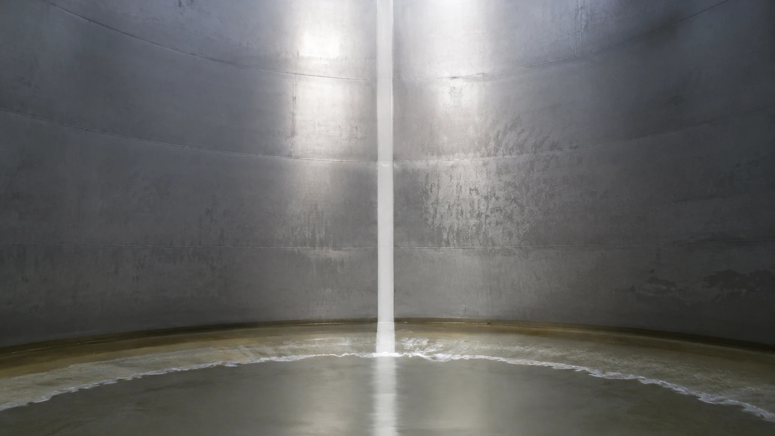
4. Stilling Wells and Bypass Chambers: In tanks with heavy agitation or internal obstructions (like agitator blades or heating coils), installing the line sensor inside a stilling well or an external bypass chamber is recommended. This provides a calm surface for the sensor and protects the probe from mechanical stress.
Limitations and Common Risks
While line sensing provides comprehensive data, it is not without risks. Understanding these limitations prevents premature equipment failure and data errors.
* Material Buildup: For contact-based line sensing (Capacitance and GWR), the accumulation of sticky or viscous media on the probe can cause "signal bridging." This leads the sensor to report a high level even when the tank is empty. Selecting probes with PTFE insulation or using high-frequency radar can mitigate this.
* Dielectric Changes: Capacitance and Radar sensors are sensitive to the dielectric constant ($ε_r$) of the medium. If a process involves switching between different chemicals with significantly different dielectric properties, the sensor may require recalibration to maintain accuracy.
* Mechanical Stress: Long probes (exceeding 3 meters) in turbulent tanks are subject to bending moments. In such cases, flexible cable probes with end weights are preferred over rigid rods to prevent snapping or damage to the tank lining.
* Vapor and Gas Layers: High-pressure steam or heavy chemical vapors can slow down the speed of electromagnetic pulses in GWR, leading to measurement errors. Advanced transmitters include vapor compensation features to correct these deviations in real-time.
Frequently Asked Questions (FAQ)
Q: Can line sensing be used for interface measurement (e.g., oil on water)?
A: Yes. Guided Wave Radar is particularly effective for interface measurement. The pulse reflects off the upper liquid (oil) and continues through to reflect off the lower liquid (water), allowing the transmitter to report both the total level and the interface level simultaneously.
Q: What is the maximum probe length for a line sensor?
A: For rigid rods, the limit is typically 6 meters due to shipping and installation constraints. For flexible cable probes, lengths can extend up to 30 or 75 meters, depending on the technology and the weight-bearing capacity of the tank roof.
Q: Does the tank material affect line sensing?
A: For capacitive sensors, a metal tank acts as the second plate of the capacitor. If the tank is plastic or fiberglass, a dual-probe sensor or a grounding strip must be used to provide a reference point.
Q: How often should line sensors be calibrated?
A: This depends on the technology. Hydrostatic and capacitive sensors may drift over time and usually require annual checks. GWR and magnetostrictive sensors are generally more stable and may only require verification every 2-3 years, depending on the criticality of the process.
Conclusion
Effective line sensing is a cornerstone of modern industrial efficiency. By moving beyond simple point detection to continuous monitoring, facilities can reduce waste, prevent overfills, and maintain tighter control over their chemical and mechanical processes. Whether utilizing the precision of magnetostrictive probes or the versatility of Guided Wave Radar, selecting the right instrument requires a balance of technical specifications and environmental awareness. For further technical support and to review specific product options for your application, refer to the resources and expert guidance available on the Main Page.