K Factor Ultrasonic Flow Meter
K Factor Ultrasonic Flow Meter: A Technical Guide to Precision Measurement
In modern industrial processing, the ability to accurately measure the movement and volume of liquids is fundamental to operational efficiency, regulatory compliance, and cost control. Among the various technologies available, ultrasonic measurement has emerged as a preferred solution due to its non-contact nature and versatility. Central to the accuracy of these systems, particularly when transitioning from simple level detection to complex flow calculation, is the "K factor."
Understanding the k factor ultrasonic flow meter relationship is essential for engineers and plant managers who utilize Ultrasonic Level Meters to monitor open channels, flumes, and weirs. This guide explores the principles of ultrasonic measurement, the mathematical significance of the K factor, and practical considerations for selecting and installing these instruments in industrial environments.
1. Principles of Ultrasonic Measurement
Before delving into the specifics of flow coefficients, it is necessary to understand how the underlying hardware functions. Ultrasonic instruments, such as those manufactured by Welk, operate on the Time-of-Flight (ToF) principle.
How the Sensor Works
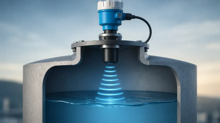
An ultrasonic transducer emits high-frequency sound pulses (typically between 20 kHz and 200 kHz). These waves travel through the air, strike the surface of the liquid, and reflect back to the sensor. The instrument measures the time interval between the emission of the pulse and the reception of the echo. Since the speed of sound in air is known (approximately 343 m/s at 20°C, though it varies with temperature), the distance to the liquid surface can be calculated with high precision.
From Level to Flow
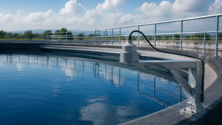
In a standard level application, the device simply subtracts the distance to the liquid from the total tank height to determine the level. However, in flow applications—specifically open-channel flow—the level (or "head") of the liquid is used to calculate the flow rate. This is where the k factor ultrasonic flow meter configuration becomes critical. By installing a primary flow element, such as a Parshall flume or a V-notch weir, the relationship between the liquid level and the flow rate becomes a predictable mathematical function.
2. Defining the K Factor in Ultrasonic Systems
In the context of flow instrumentation, the "K factor" generally refers to a calibration constant that relates the raw sensor signal to a specific physical quantity. Depending on the specific type of ultrasonic meter being used, the K factor serves different purposes:
* Open Channel Flow: For systems using ultrasonic level sensors to calculate flow, the K factor is often a coefficient in the flow formula (e.g., $Q = K imes H^n$), where $Q$ is the flow rate, $H$ is the head/level, and $K$ and $n$ are constants determined by the geometry of the flume or weir.
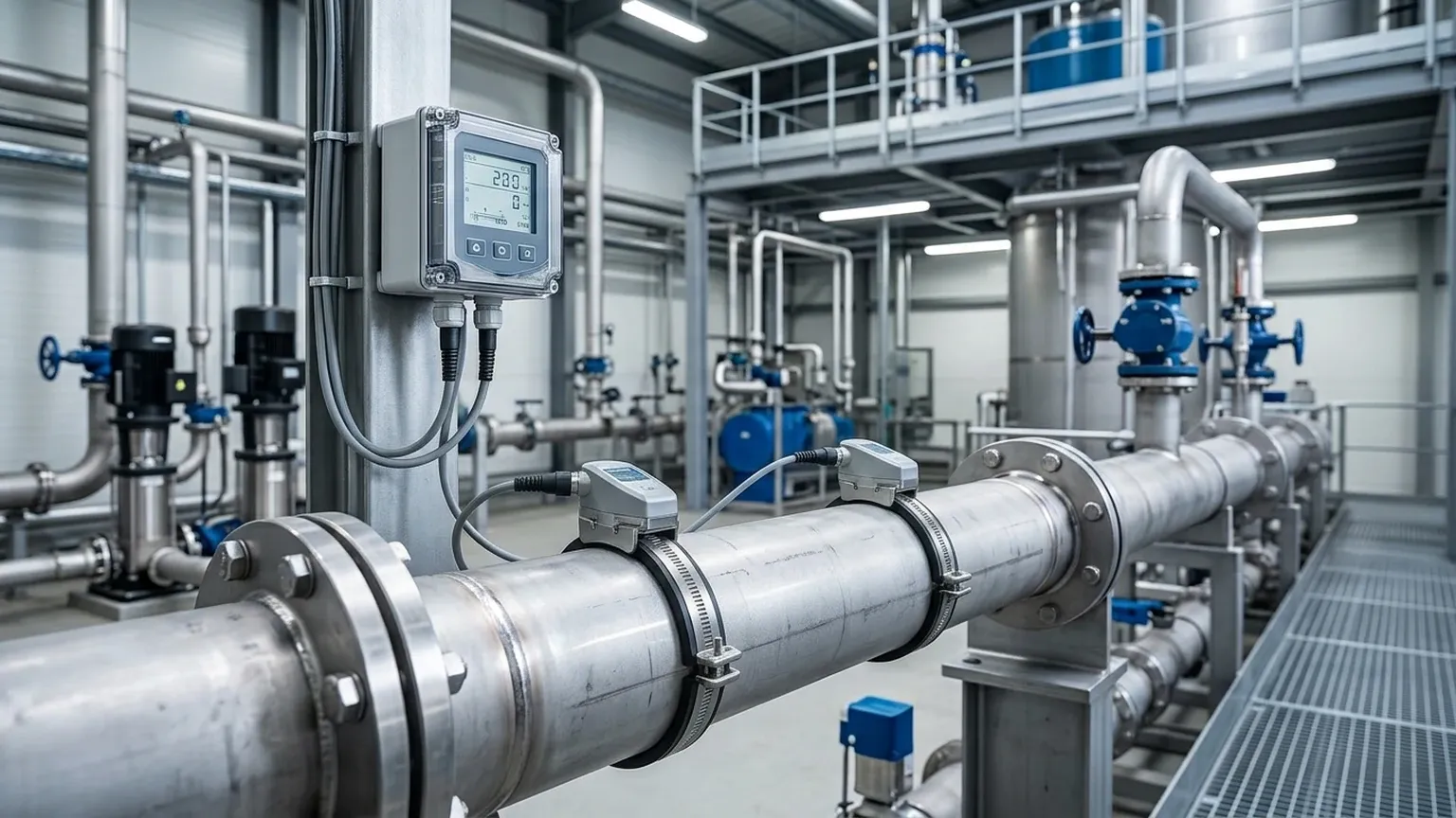
* Inline Transit-Time Meters: In closed-pipe ultrasonic flow meters, the K factor represents the number of pulses generated by the meter per unit of volume (e.g., pulses per liter). This is determined during factory calibration against a master meter.
* Scaling and Calibration: The K factor allows the electronics to convert a linear distance measurement into a volumetric flow measurement. Without an accurate K factor, even the most precise distance measurement will result in incorrect flow data.
3. Selecting the Right Ultrasonic Level Meters for Flow Applications
Choosing the correct instrument requires an analysis of the fluid properties, the physical environment, and the required accuracy. Welk provides a range of Ultrasonic Level Meters designed to handle various industrial challenges.
Key Evaluation Criteria
When evaluating a k factor ultrasonic flow meter setup, consider the following factors:
1. Measurement Range: Ensure the sensor's range covers both the minimum and maximum expected head levels in the flume. Most industrial sensors range from 0.25 meters to 15 meters.
2. Beam Angle: A narrower beam angle (e.g., 5° to 10°) is preferable for flow applications to avoid false echoes from the walls of narrow flumes or mounting brackets.
3. Temperature Compensation: Since the speed of sound changes with air temperature, the meter must have an integrated temperature sensor to adjust the K factor calculations in real-time.
4. Signal Processing: Advanced algorithms are required to filter out noise from turbulence, foam, or steam, which can otherwise lead to erratic flow readings.
Selection Table: Ultrasonic vs. Alternative Technologies
| Feature | Ultrasonic (Non-Contact) | Hydrostatic Pressure | Radar (Microwave) |
| :— | :— | :— | :— |
| Installation | Top-mounted, easy | Submerged, complex | Top-mounted, easy |
| Maintenance | Low (no moving parts) | Medium (fouling risk) | Low |
| Accuracy | ±0.25% of range | ±0.1% to 0.5% | ±1 mm to 3 mm |
| Cost | Cost-effective | Moderate | Higher |
| Suitability | Open channels, tanks | Deep wells, pressurized tanks | Corrosive/Steam environments |
4. Installation Considerations and Best Practices
The accuracy of a k factor ultrasonic flow meter is highly dependent on proper installation. Even a high-quality Welk sensor will provide inaccurate data if the physical setup is flawed.
Positioning and Dead Zones
Every ultrasonic sensor has a "dead zone" (also known as the blanking distance) directly beneath the transducer face where it cannot measure. This typically ranges from 100 mm to 500 mm depending on the frequency. The sensor must be mounted high enough so that even at maximum flow (maximum head), the liquid level never enters this dead zone.
Alignment
The transducer must be mounted perfectly perpendicular to the liquid surface. A tilt of even a few degrees can cause the reflected signal to miss the receiver, leading to signal loss or "hunting."
Flow Profile and Turbulence
For open-channel flow, the level measurement should be taken at a specific distance upstream from the weir or flume (usually 3 to 4 times the maximum head). This ensures that the measurement is taken in a zone of laminar flow, away from the "draw-down" effect that occurs as the liquid accelerates over the crest of the weir.
5. Common Risks and Limitations
While Ultrasonic Level Meters are robust, they are not universal solutions. Engineers must be aware of the following limitations:
* Heavy Foam: Thick foam on the surface of the liquid can absorb the ultrasonic pulse rather than reflecting it. In such cases, a radar-based level meter or a hydrostatic transmitter may be more appropriate.
* Vapor and Vacuum: Ultrasonic waves require a medium (air or gas) to travel. They cannot function in a vacuum. High concentrations of heavy vapors can also change the speed of sound, requiring specialized calibration.
* Extreme Turbulence: Rapidly fluctuating surfaces can scatter the signal. This can often be mitigated by using a stilling well or by adjusting the damping/averaging settings in the meter’s software.
6. Calibration and the K Factor Calculation
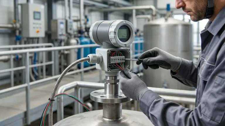
Calibrating a k factor ultrasonic flow meter involves entering the specific geometry of the primary flow element into the transmitter's software. Most modern Welk instruments come pre-programmed with standard flume and weir curves (e.g., Parshall, Palmer-Bowlus, V-notch).
If using a non-standard channel, a custom K factor must be calculated. This is typically done by:
1. Measuring the physical dimensions of the channel.
2. Using fluid dynamics formulas to establish the head-to-flow relationship.
3. Entering the resulting coefficient as the K factor in the meter’s configuration menu.
Periodic verification is recommended. This involves manually measuring the head with a staff gauge and comparing the meter’s calculated flow against the theoretical flow for that head level.
7. Frequently Asked Questions (FAQs)
Q: Can I use a standard level meter as a flow meter?
A: Yes, provided the meter has the software capability to perform flow calculations (integrating flume/weir formulas) and you have a primary flow element installed.
Q: How often should the K factor be recalibrated?
A: In stable environments, the K factor does not change. However, you should verify the accuracy annually or whenever the primary flow element (flume/weir) is cleaned or modified.
Q: Does pipe diameter affect the K factor in ultrasonic meters?
A: In transit-time (inline) meters, yes. The pipe’s internal diameter is a critical variable in calculating the K factor. In open-channel level-to-flow applications, the width of the flume is the equivalent critical variable.
Q: What happens if the temperature sensor fails?
A: If the temperature compensation fails, the meter will assume a default temperature (usually 20°C). This can lead to errors of approximately 0.17% per degree Celsius of deviation from the actual air temperature.
Conclusion
The integration of a k factor ultrasonic flow meter system offers a reliable, low-maintenance solution for industrial liquid monitoring. By understanding the relationship between ultrasonic ToF principles and the mathematical constants used to scale those measurements, engineers can ensure high levels of accuracy in their processes. Whether you are managing wastewater treatment, chemical processing, or irrigation, selecting the appropriate Ultrasonic Level Meters and applying rigorous installation standards is the key to long-term operational success.