Ultrasonic Level Sensor Connection
Ultrasonic Level Sensor Connection: A Comprehensive Industrial Guide
In modern industrial automation, the accuracy of inventory management and process control depends heavily on the reliability of field instrumentation. Among the various technologies available, Ultrasonic Level Meters have become a standard for non-contact measurement in water treatment, chemical processing, and food production. However, the performance of these instruments is not solely determined by the sensor's internal electronics; it is fundamentally tied to the quality of the ultrasonic level sensor connection—both mechanical and electrical.
This guide provides an engineering perspective on how to properly integrate ultrasonic sensors into industrial systems, covering measurement principles, mounting configurations, and wiring protocols to ensure long-term operational stability.
Understanding the Measurement Principle
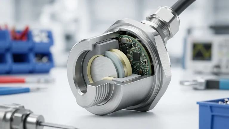
Before addressing the specifics of a connection, it is essential to understand how an ultrasonic level sensor interacts with its environment. These devices operate on the Time-of-Flight (ToF) principle. A piezoelectric crystal within the sensor transducer converts electrical energy into high-frequency sound pulses. These pulses travel through the air, reflect off the surface of the target medium (liquid or solid), and return to the transducer.
The distance ($D$) is calculated using the formula:
$D = (c \times t) / 2$
Where:
* c is the speed of sound in the medium (typically air).
* t is the total time elapsed between transmission and reception.
Because the speed of sound is influenced by air temperature—changing by approximately 0.17% per degree Celsius—professional-grade sensors from manufacturers like Welk include integrated temperature compensation. An incorrect mechanical ultrasonic level sensor connection that exposes the transducer to localized heat sources or prevents it from accurately sensing the ambient air temperature will result in significant measurement errors.
Mechanical Connection Types and Selection
The mechanical connection serves two purposes: it secures the device to the vessel and ensures the transducer is oriented perpendicular to the product surface. Choosing the wrong mounting interface can lead to signal loss or physical damage to the instrument.
1. Threaded Connections
Threaded mounts are the most common for small-to-medium-sized tanks and open-channel applications. They are typically available in NPT (National Pipe Thread) or G (ISO 228) standards.
* Best for: Plastic tanks, sumps, and small metal vessels.
* Consideration: Use Teflon tape or appropriate sealants to ensure a gas-tight fit, especially in applications where vapors might corrode external wiring.
2. Flanged Connections
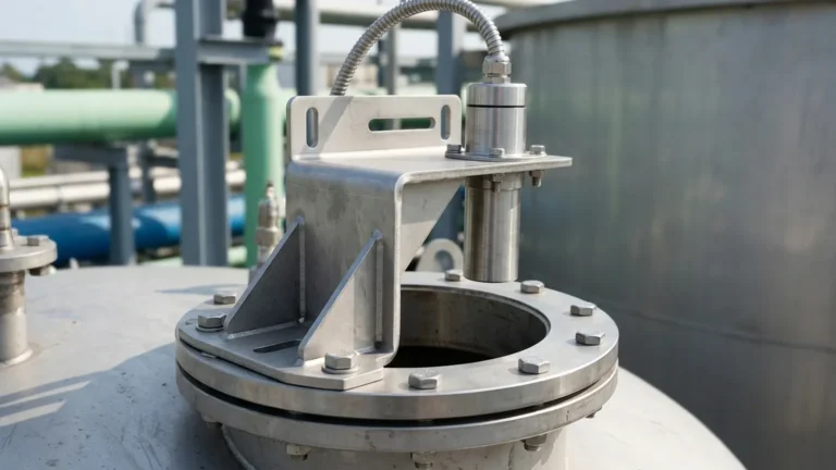
For pressurized vessels or applications involving corrosive chemicals, flanged connections (ANSI, DIN, or JIS standards) are preferred. Flanges provide a robust seal and allow for easier removal during maintenance.
* Best for: Chemical storage tanks and high-pressure environments.
* Consideration: Ensure the flange material (e.g., Stainless Steel, PVC, or PTFE-coated) is compatible with the process vapors.
3. Bracket and Suspension Mounting
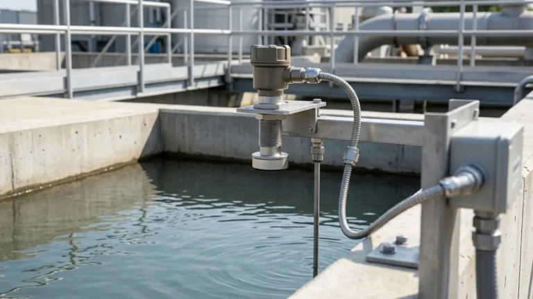
In open-air applications like reservoir monitoring or wastewater flumes, sensors are often mounted on stainless steel brackets or suspended via a heavy-duty cable.
* Best for: Open channels, rivers, and wet wells.
* Consideration: Ensure the sensor is stable and not prone to swaying, which can cause the ultrasonic beam to miss the target.
Connection Selection Table
| Application Environment | Recommended Connection | Primary Advantage |
| :— | :— | :— |
| Standard Water Storage | Threaded (G2" or 2" NPT) | Cost-effective and simple installation |
| Corrosive Chemical Tank | DN80 or DN100 Flange | High chemical resistance and sealing |
| Wastewater Wet Well | Wall-mount Bracket | Easy access for cleaning/maintenance |
| High-Vibration Machinery | Reinforced Flange | Prevents mechanical fatigue of the sensor |
Electrical Ultrasonic Level Sensor Connection
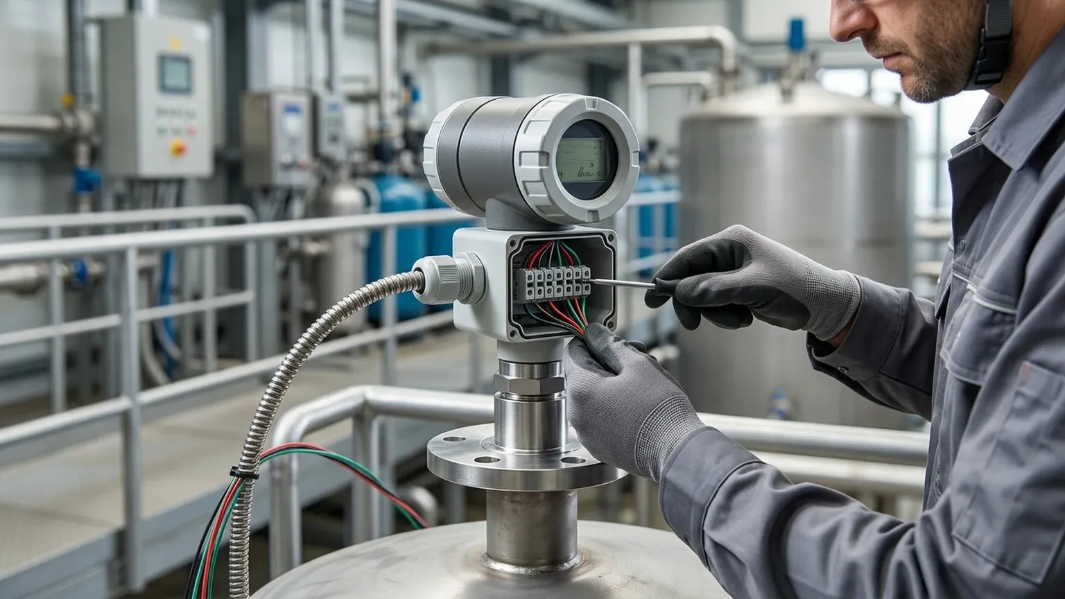
The electrical interface facilitates both power supply and data transmission. Modern industrial sensors typically utilize one of three primary wiring configurations.
Two-Wire (Loop-Powered)
In a 2-wire configuration, the 4-20mA DC signal and the power supply share the same pair of wires. This is the industry standard for energy-efficient installations.
* Voltage: Typically 12-36V DC.
* Advantage: Reduced wiring costs and simplified integration with PLC/DCS analog input cards.
Three-Wire and Four-Wire
These configurations separate the power supply from the output signal. Four-wire sensors often allow for AC power (e.g., 110V/220V) and provide more power to the transducer for measuring difficult materials like solids or dusty environments.
* Advantage: Stronger pulse emission and the ability to drive internal relays for local pump control.
Digital Communication Protocols
Beyond simple analog signals, the ultrasonic level sensor connection often includes digital layers for remote diagnostics and configuration:
* HART: Superimposes a digital signal over the 4-20mA loop.
* RS485/Modbus: Ideal for daisy-chaining multiple sensors over long distances (up to 1,200m or 3,937 ft).
* Profibus/Foundation Fieldbus: Used in complex plant-wide automation architectures.
Critical Installation Considerations
Even the highest quality Ultrasonic Level Meters will fail if the physical installation ignores the physics of sound waves. Engineers must account for the following factors during the connection process:
The Blocking Distance (Dead Zone)
Every ultrasonic sensor has a "dead zone" immediately below the transducer face (typically 0.25m to 0.5m depending on the model). The sensor cannot process reflections within this range. The mechanical connection must be designed so that the highest possible liquid level never enters this zone.
Beam Angle and Obstructions
Ultrasonic pulses expand in a conical shape (usually 5° to 12°). The connection point must be positioned to ensure the beam path is clear of internal tank structures such as:
* Ladders and pipes.
* Agitators or mixers.
* Inflow streams (which create turbulence and noise).
Nozzle Geometry
If mounting the sensor on a pipe nozzle, the height-to-diameter ratio is critical. If the nozzle is too tall or too narrow, the ultrasonic pulse will reflect off the nozzle walls rather than the liquid surface, creating a "false echo."
Common Risks and Mitigation
1. Signal Interference (EMI): Electrical noise from variable frequency drives (VFDs) can disrupt the sensor signal. Always use shielded twisted-pair cables for the electrical connection and ensure the shield is grounded at the controller end only.
2. Condensation and Build-up: In humid environments, water droplets can form on the transducer face. Selecting a sensor with a self-cleaning face or installing the unit at a slight angle (if the surface is turbulent) can help, though perpendicularity is generally required for flat surfaces.
3. Temperature Gradients: If the tank is under direct sunlight, the air space inside can become significantly hotter than the sensor's mounting point. Using a sunshade can prevent the internal temperature sensor from providing inaccurate compensation data.
Confirmation Checklist Before Commissioning
Before finalizing the ultrasonic level sensor connection, project teams should confirm the following:
* Material Compatibility: Is the sensor body and gasket material resistant to the process medium?
* Range Matching: Does the sensor's maximum range exceed the tank depth by at least 15-20% to account for signal attenuation?
* Power Requirements: Does the PLC/controller provide enough current to drive the sensor, especially during the startup surge?
* Calibration: Has the "Empty" (4mA) and "Full" (20mA) distance been mapped correctly to the specific tank geometry?
Frequently Asked Questions (FAQ)
Q: Can I use an ultrasonic sensor in a vacuum?
A: No. Ultrasonic waves require a medium (gas/air) to travel. In a vacuum, there are no molecules to transmit the sound vibration. For vacuum applications, radar level meters are the appropriate choice.
Q: How do I handle foam on the liquid surface?
A: Light, airy foam can absorb the ultrasonic signal, leading to a "Lost Echo" error. If foam is persistent, consider a higher-power sensor or switching to a contact technology like a magnetic level gauge or a hydrostatic transmitter.
Q: What is the maximum cable length for a 4-20mA connection?
A: For a standard 24V DC loop, you can typically run cables up to 1,000 meters (3,280 ft), provided you use high-quality shielded cable and account for the total loop resistance (including the PLC input impedance).
Conclusion
Achieving a reliable ultrasonic level sensor connection requires a balanced approach to mechanical stability and electrical integrity. By understanding the ToF principle and respecting the physical limitations of acoustic measurement—such as beam angles and dead zones—engineers can implement level measurement solutions that require minimal maintenance and provide high accuracy. For specialized applications or custom OEM requirements, consulting with a manufacturer like Welk ensures that the instrument's specifications align perfectly with the operational environment.