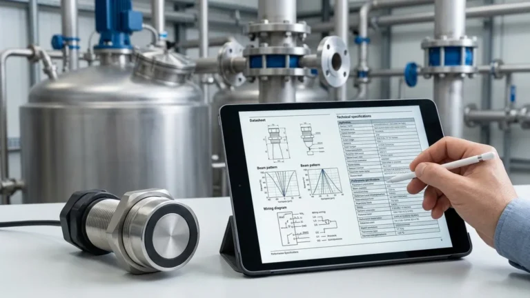
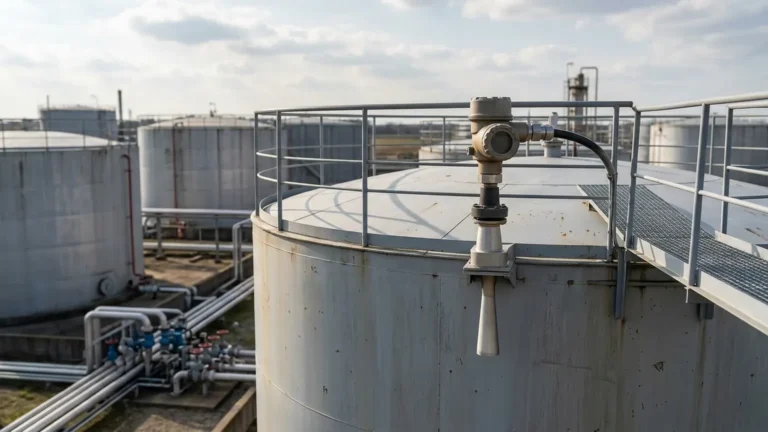
Ultrasonic Level Sensor Modbus
Ultrasonic Level Sensor Modbus: A Comprehensive Engineering Guide
In the landscape of industrial automation, the ability to accurately monitor liquid and solid levels without physical contact is a cornerstone of process efficiency and safety. Ultrasonic Level Meters have emerged as a primary solution for these needs, offering a balance of reliability and cost-effectiveness. However, the raw measurement data is only valuable if it can be seamlessly integrated into a facility's control architecture. This is where the ultrasonic level sensor modbus interface becomes critical.
As a professional manufacturer of industrial level measurement instruments, Welk provides advanced ultrasonic solutions designed to meet the rigorous demands of water treatment, chemical processing, and industrial automation. This guide explores the technical principles, integration strategies, and selection criteria for ultrasonic level sensors utilizing the Modbus protocol.
Understanding the Measurement Principle
Before selecting a communication protocol, it is essential to understand how the underlying hardware functions. Ultrasonic level measurement is based on the "Time of Flight" (ToF) principle.
The Acoustic Pulse
An ultrasonic transducer, typically constructed from piezoelectric crystals, emits a high-frequency acoustic pulse. This pulse travels through the air (or the medium in the tank headspace) until it strikes the surface of the material being measured.
Reflection and Detection
Upon hitting the surface, a portion of the sound energy is reflected back toward the sensor as an echo. The transducer then switches to a receiving mode to detect this returning signal. The internal electronics of the sensor measure the exact time elapsed between the emission of the pulse and the reception of the echo.
Distance Calculation
The distance ($D$) from the sensor to the material surface is calculated using the formula:
$$D = \frac{c \times t}{2}$$
Where:
* $c$ is the speed of sound in the medium (approximately 344 m/s in air at 20°C).
* $t$ is the total time for the round trip.
Since the speed of sound is significantly affected by air temperature, professional-grade sensors like those from Welk include integrated temperature compensation. This ensures that the calculated distance remains accurate even as environmental conditions fluctuate within the tank.
Integration of Modbus Protocol in Ultrasonic Level Meters
While traditional 4-20mA analog signals are still widely used, the transition to digital communication via the ultrasonic level sensor modbus interface offers significant advantages in data density and diagnostic capabilities.
Why Modbus RTU?
Modbus RTU (Remote Terminal Unit) over an RS485 physical layer is the industry standard for sensor-to-PLC communication. It is a master-slave protocol that allows a single controller (the Master) to poll multiple sensors (the Slaves) on the same twisted-pair cable.
Key benefits include:
* Multi-drop Capability: Up to 32 devices (or more with repeaters) can be connected on a single bus, drastically reducing wiring costs compared to individual 4-20mA runs.
* Data Integrity: Digital communication is less susceptible to electromagnetic interference (EMI) than analog signals, ensuring the value received by the PLC is exactly what the sensor measured.
* Rich Data Access: Beyond just the level value, Modbus allows the user to read secondary variables such as internal temperature, signal strength (echo quality), and diagnostic error codes.
Register Mapping
An ultrasonic level sensor modbus typically organizes its data into "Holding Registers" (Read/Write) and "Input Registers" (Read Only). A standard register map might include:
| Register Address | Data Type | Description |
| :— | :— | :— |
| 0x0001 | Float | Measured Distance (m/ft) |
| 0x0003 | Float | Measured Level (m/ft) |
| 0x0005 | Float | Current Temperature (°C/°F) |
| 0x0007 | Integer | Signal Strength (0-100%) |
| 0x0008 | Integer | Device Status/Error Code |
| 0x0100 | Integer | Slave ID (Address) |
| 0x0101 | Integer | Baud Rate Configuration |
Key Selection Criteria for Industrial Applications
Choosing the right ultrasonic level sensor modbus requires a thorough evaluation of both the physical environment and the digital requirements. Engineers should use the following table as a starting point for technical comparison:
Practical Selection Table
| Feature | Standard Industrial | Heavy-Duty/Chemical | Long-Range Application |
| :— | :— | :— | :— |
| Measurement Range | 0.3m to 5m (1ft to 16ft) | 0.4m to 10m (1.3ft to 33ft) | 0.5m to 15m+ (1.6ft to 50ft+) |
| Accuracy | ±0.5% of Full Scale | ±0.25% of Full Scale | ±0.25% of Full Scale |
| Housing Material | ABS / Nylon | PVDF / PTFE | Reinforced Polymer |
| Beam Angle | 8° – 12° | 5° – 8° | 6° – 10° |
| Communication | Modbus RTU / 4-20mA | Modbus RTU / 4-20mA / HART | Modbus RTU / RS485 |
| Ingress Protection | IP65 / IP66 | IP67 / IP68 | IP67 |
Evaluation Factors
1. Chemical Compatibility: For acidic or alkaline environments, sensors with PVDF or PTFE-coated transducers are mandatory to prevent corrosion.
2. Beam Angle: A narrower beam angle is preferable in narrow tanks or tanks with internal obstructions (ladders, pipes) to avoid false echoes.
3. Blocking Distance (Blind Zone): Every ultrasonic sensor has a minimum distance near the transducer face where it cannot measure. Ensure the maximum high-level of your tank does not enter this zone.
4. Resolution: For precise dosing applications, look for sensors offering millimeter-level resolution.
Installation Best Practices and Geometric Considerations
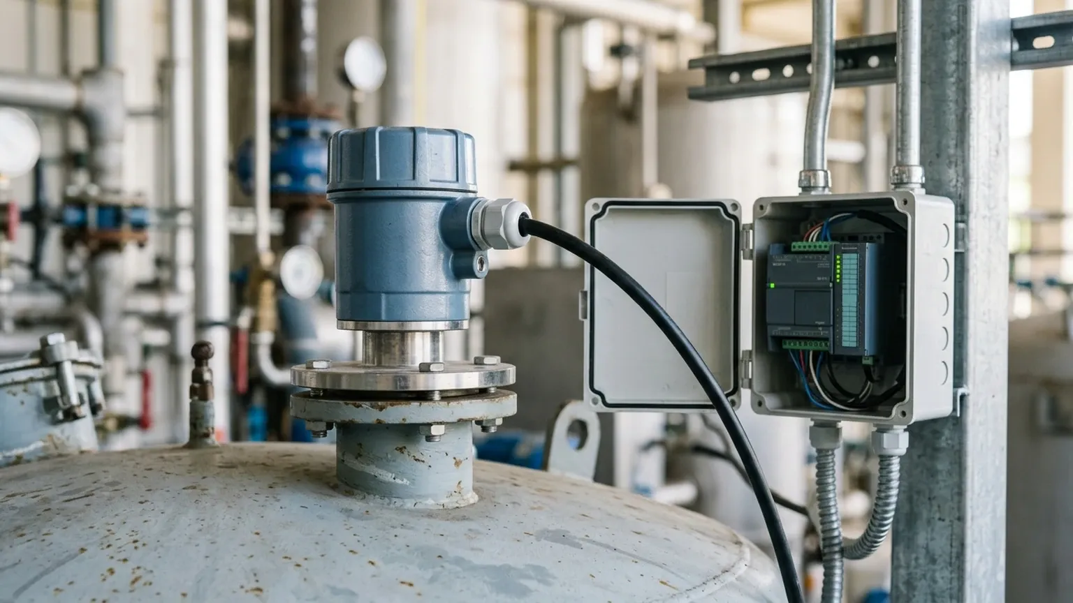
Correct installation is the most influential factor in the performance of an ultrasonic level sensor modbus. Even the most advanced sensor will fail if acoustic physics are ignored.
Positioning and Alignment
* Perpendicularity: The sensor face must be perfectly parallel to the liquid surface. A tilt of even a few degrees can cause the acoustic pulse to reflect away from the transducer, resulting in signal loss.
* Wall Proximity: Avoid mounting the sensor too close to the tank wall. A general rule is to maintain a distance of at least 1/6th of the tank height from the wall to prevent side-wall interference.
* Inflow Avoidance: Never install the sensor directly above the point where liquid enters the tank. Turbulence and air entrainment at the inlet will scatter the ultrasonic signal.
Obstruction Management
Internal structures like heating coils, agitators, or support beams can create "false echoes." While many Welk sensors include "False Echo Suppression" software to mask these signals, it is best practice to position the sensor in a clear path to the liquid surface.
The Blind Zone (Blocking Distance)
If the liquid level rises into the blind zone (typically 0.2m to 0.5m depending on the range), the sensor will provide erratic readings or a "full" error. If the tank must be filled to the very top, consider using a mounting well or a standpipe to raise the sensor above the maximum liquid level.
Limitations and Environmental Constraints
While versatile, ultrasonic technology is not a universal solution. Engineers must be aware of the following limitations:
1. Vacuum Conditions: Sound requires a medium to travel. In a vacuum, ultrasonic sensors cannot function. For such applications, radar level meters are the appropriate choice.
2. High Pressure/Temperature: Significant changes in pressure or temperature alter the density of the air, which changes the speed of sound. While temperature compensation helps, extreme conditions (e.g., >2 bar or >80°C) may exceed the sensor's compensatory limits.
3. Heavy Foam: Thick, dense foam acts as an acoustic absorber. It soaks up the ultrasonic pulse rather than reflecting it, leading to a "Loss of Echo" (LOE) signal.
4. Dust and Vapor: Heavy dust in grain silos or thick steam in hot water tanks can attenuate the signal. In these cases, a lower frequency sensor with higher power is required, or a transition to radar technology may be necessary.
Frequently Asked Questions (FAQ)
Q: How do I change the Modbus Slave ID of the sensor?
A: Most sensors are shipped with a default Slave ID (usually 1). This can be changed by writing the new ID value to the designated configuration register using a Modbus Master tool or through the sensor's local HMI if equipped.
Q: Can I use a standard shielded twisted pair for the Modbus connection?
A: Yes, RS485 communication requires a shielded twisted pair. The shield should be grounded at one end (usually the PLC side) to prevent ground loops while protecting the signal from noise.
Q: What happens if the sensor loses its echo?
A: The sensor will typically hold the last valid value for a configurable "fail-safe" time. If the echo does not return, the Modbus status register will flag an error, and the output value will jump to a pre-defined fail-safe state (e.g., 0 or maximum range).
Q: Is the ultrasonic level sensor modbus suitable for solids?
A: Yes, but the range is typically reduced by 50% compared to liquids because solid surfaces (like grain or powders) are not flat and scatter the sound energy more significantly.
Conclusion
The integration of an ultrasonic level sensor modbus into your industrial process provides a robust, digital-ready solution for non-contact level monitoring. By understanding the acoustic principles, adhering to strict installation guidelines, and selecting the appropriate hardware for your chemical and environmental conditions, you can ensure long-term accuracy and system reliability.
For those seeking to optimize their liquid management systems with high-precision instrumentation, Welk offers a diverse range of Ultrasonic Level Meters tailored for global industrial standards. Whether you are managing a simple water tank or a complex chemical reactor, choosing the right digital interface is the first step toward a smarter, more connected facility.