Ultrasonic Level Sensor Principle
Understanding the Ultrasonic Level Sensor Principle for Industrial Applications
In the field of industrial process control, accurate level measurement is essential for inventory management, operational safety, and process efficiency. Among the various technologies available, ultrasonic level measurement has emerged as a preferred non-contact solution for a wide range of liquid and solid applications. As a professional manufacturer, Welk provides advanced Ultrasonic Level Meters designed to meet the rigorous demands of water treatment, chemical processing, and industrial automation.
Selecting the right instrumentation requires a thorough understanding of the underlying physics and the environmental factors that influence performance. This guide explores the ultrasonic level sensor principle, technical specifications, and practical installation strategies to ensure reliable data in complex industrial environments.
The Ultrasonic Level Sensor Principle: How It Works
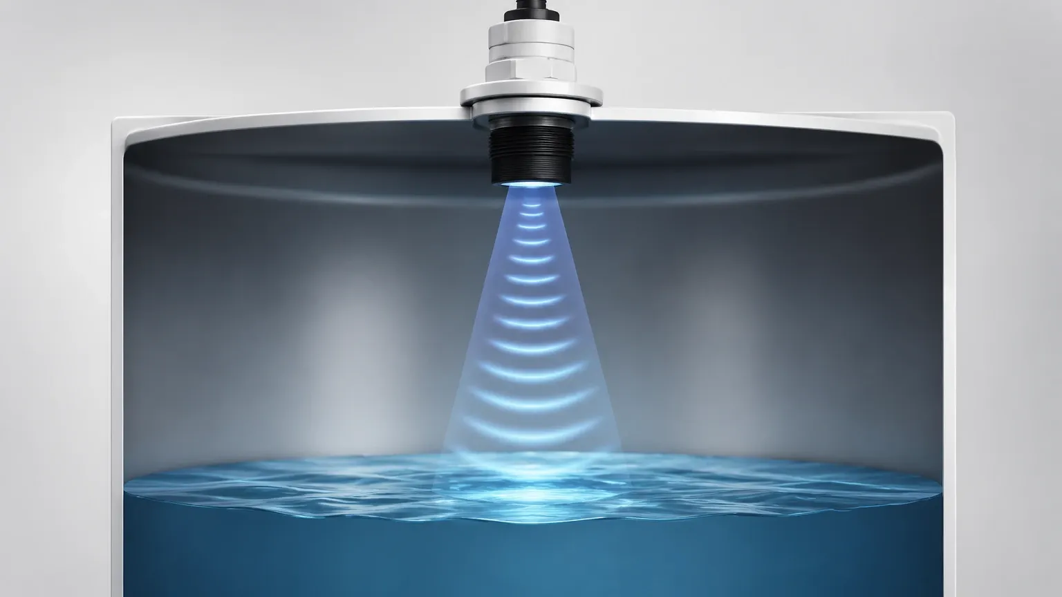
The fundamental ultrasonic level sensor principle is based on the "time-of-flight" (ToF) measurement of sound waves. Unlike contact-based methods such as float switches or bubblers, ultrasonic sensors operate by emitting high-frequency acoustic pulses that travel through the air to the surface of the medium being measured.
1. Pulse Emission and Reflection
The process begins with a transducer, typically containing one or more piezoelectric crystals. When an electrical pulse is applied to these crystals, they vibrate at a specific frequency (usually between 20 kHz and 200 kHz), generating an ultrasonic wave. This wave travels from the sensor face toward the target material.
2. The Time-of-Flight Calculation
When the sound wave hits the surface of the liquid or solid, a portion of the energy is reflected back toward the sensor as an echo. The sensor electronics record the exact time the pulse was emitted and the exact time the echo was received. The distance between the sensor and the medium surface is then calculated using the following formula:
Distance = (Speed of Sound × Time Delay) / 2
The division by two is necessary because the time recorded represents the round-trip travel of the pulse (from sensor to surface and back).
3. Determining Level from Distance
To provide a "level" reading rather than just a "distance" reading, the instrument must be programmed with the total height of the tank or vessel (the "Empty Distance"). The level is calculated as:
Level = Tank Height – Measured Distance
By integrating this logic into a microprocessor, the device can output standardized signals, such as 4-20mA, RS485 (Modbus), or HART, which are then used by PLC or SCADA systems for monitoring and control.
Key Components of an Ultrasonic Level Meter
To execute the ultrasonic level sensor principle effectively, an instrument consists of several critical sub-systems:
* Transducer: The "heart" of the device, responsible for converting electrical energy into mechanical sound waves and vice versa. Welk utilizes high-sensitivity transducers to ensure even weak echoes from turbulent surfaces are captured.
* Signal Processing Electronics: Advanced algorithms are used to filter out noise caused by tank walls, agitators, or ladders. This is often referred to as "false echo suppression."
* Temperature Sensor: Because the speed of sound in air changes with temperature, a built-in thermistor or RTD is used to provide real-time compensation, ensuring accuracy remains consistent as ambient conditions fluctuate.
* Housing: Industrial-grade housings (often IP66, IP67, or IP68) protect the electronics from moisture, dust, and corrosive vapors.
Technical Evaluation Criteria for Selection
When choosing an ultrasonic level meter, engineers must look beyond the basic principle and evaluate specific performance parameters.
Measurement Range and Frequency
Lower frequency sensors (e.g., 20-40 kHz) have longer wavelengths and can travel further, making them suitable for deep tanks or silos (up to 30 or 40 meters). Higher frequency sensors (e.g., 60-100 kHz) offer better resolution and smaller "dead zones," making them ideal for short-range measurements in small tanks.
The "Dead Zone" (Blocking Distance)
The dead zone is a region directly in front of the transducer face where the sensor cannot accurately measure. This occurs because the transducer needs a fraction of a millisecond to stop vibrating after emitting a pulse before it can listen for the return echo. Typical dead zones range from 0.2 meters to 0.8 meters (approx. 8 to 31 inches), depending on the frequency.
Beam Angle
The ultrasonic pulse does not travel in a straight line; it spreads out in a cone. The beam angle (usually between 5° and 12°) determines the footprint of the signal at a given distance. A narrower beam angle is preferable in narrow tanks or vessels with internal obstructions like cooling coils or support beams.
Selection Table: Application vs. Instrument Features
| Application Type | Recommended Feature | Reason |
| :— | :— | :— |
| Wastewater / Open Channels | IP68 Rating, Integrated Temp Compensation | Exposure to humidity and diurnal temperature swings. |
| Chemical Storage Tanks | PVDF or PTFE Transducer Face | Resistance to corrosive vapors (acids/alkalis). |
| Solids / Grain Silos | High Power, Low Frequency (20kHz) | Sound waves must penetrate dust and reflect off uneven surfaces. |
| Hazardous Areas (Oil/Gas) | Explosion-proof (Ex d) or Intrinsically Safe (Ex ia) | Compliance with ATEX/IECEx safety standards. |
| Small Process Vessels | High Frequency, Small Dead Zone | Maximizes usable tank volume in tight spaces. |
Installation Considerations and Best Practices
Correct installation is as important as the ultrasonic level sensor principle itself. Even the most advanced sensor will fail if placed incorrectly.
1. Perpendicular Alignment: The sensor face must be installed perfectly parallel to the liquid surface. If the sensor is tilted, the echo may reflect away from the transducer, resulting in a "Loss of Echo" (LOE) error.
2. Avoid the Filling Stream: Never install the sensor directly above the inlet pipe. The falling liquid or solid will intercept the ultrasonic pulse and provide a false high-level reading.
3. Distance from Walls: To prevent interference from wall reflections (multi-path echoes), the sensor should be placed at least 20-30 cm away from the tank wall for every meter of depth.
4. Standpipe Usage: In tanks with heavy foam or extreme turbulence, the sensor can be mounted on a stilling well or standpipe. This pipe acts as a waveguide, providing a smooth surface for the measurement, though the pipe must be vented and have a smooth internal diameter.
5. Sunlight Protection: For outdoor installations, a sunshade is recommended. Direct sunlight can heat the sensor body to a temperature significantly higher than the actual air temperature, leading to inaccurate temperature compensation and measurement errors.
Limitations and Environmental Factors
While highly versatile, the ultrasonic level sensor principle has physical limitations that must be acknowledged during the engineering phase:
* Vacuum Conditions: Sound requires a medium (air or gas) to travel. Ultrasonic sensors cannot function in a vacuum.
* High Pressure: In high-pressure environments, the density of the gas changes, which significantly alters the speed of sound and can attenuate the signal.
* Heavy Foam: Thick, protein-based foam can absorb the ultrasonic pulse rather than reflecting it. In such cases, radar or hydrostatic transmitters may be more appropriate.
* Vapor and Gas Layers: If the tank contains a gas other than air (e.g., Carbon Dioxide or Nitrogen), the speed of sound will differ from the factory-calibrated air speed. Users must manually enter the specific gas velocity into the sensor settings.
* Extreme Turbulence: Rapidly boiling liquids or heavy agitation can scatter the sound wave. Advanced software filtering can mitigate this, but it may slow down the response time.
Frequently Asked Questions (FAQs)
Q1: Can ultrasonic sensors measure solids?
Yes, but with caveats. Solids like grain, sand, or plastic pellets often form a conical shape (angle of repose), which scatters the echo. Sensors for solids typically require higher power and lower frequencies to compensate for this scattering and the potential for dust.
Q2: How does temperature affect accuracy?
The speed of sound in air increases by approximately 0.6 meters per second for every degree Celsius increase in temperature. Without compensation, a 10°C change could result in a measurement error of nearly 2%. Welk sensors include integrated temperature probes to automate this correction.
Q3: What is the difference between a 2-wire and 4-wire ultrasonic meter?
A 2-wire meter is loop-powered, meaning the same two wires provide power and carry the 4-20mA signal. These are easier to install but have less power for signal processing. A 4-wire meter has separate power and signal lines, allowing for higher-power pulses and better performance in challenging environments.
Q4: How do I handle a "Loss of Echo" (LOE) alarm?
First, check for physical obstructions or heavy foam. Ensure the transducer face is clean and free of condensation or buildup. If the surface is turbulent, increasing the "damping" or "averaging" time in the sensor settings may stabilize the reading.
Conclusion
By leveraging the ultrasonic level sensor principle, industrial facilities can achieve reliable, non-contact measurement that reduces maintenance costs and improves safety. Understanding the relationship between sound velocity, temperature, and beam geometry allows engineers to select the most effective Ultrasonic Level Meters for their specific needs.
Whether managing a municipal water reservoir or a complex chemical storage farm, Welk’s range of level instrumentation provides the accuracy and durability required for modern industrial automation. For successful implementation, always prioritize proper mounting, account for the dead zone, and ensure the environmental conditions align with the physical capabilities of ultrasonic technology.