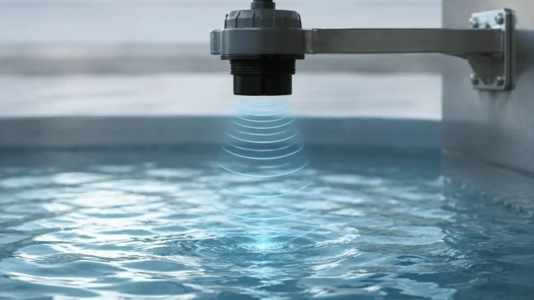
Ultrasonic Level Symbol
Understanding the Ultrasonic Level Symbol in Industrial Instrumentation
In the complex landscape of industrial process control, clear communication through standardized documentation is essential. For engineers, technicians, and system integrators, the ultrasonic level symbol serves as a critical shorthand on Piping and Instrumentation Diagrams (P&ID). These symbols ensure that the design intent for level measurement is universally understood, from the initial drafting phase to installation and long-term maintenance.
Ultrasonic Level Meters are non-contact instruments used extensively across water treatment, chemical processing, and industrial automation. Understanding how these devices are represented in technical drawings is the first step in ensuring a successful integration into a control loop.
Measurement Principles of Ultrasonic Technology
Before diving into the specific symbols used in documentation, it is vital to understand the physics of the device being represented. Ultrasonic level measurement is based on the "time-of-flight" (TOF) principle.
The Transducer and Pulse Emission
An ultrasonic sensor contains a piezoelectric crystal that converts electrical energy into mechanical vibrations. These vibrations create high-frequency sound waves (typically between 20 kHz and 200 kHz) that are emitted in pulses toward the surface of the medium being measured.
Echo Return and Calculation
Once the sound waves hit the surface of the liquid or solid, they are reflected back to the sensor. The instrument measures the time interval between the emission of the pulse and the reception of the echo. Since the speed of sound in air is relatively constant—approximately 343 meters per second (1,125 feet per second) at 20°C (68°F)—the distance can be calculated using the formula:
Distance = (Speed of Sound × Time) / 2
By subtracting this distance from the total height of the tank (the calibration offset), the device determines the actual level of the material. Modern ultrasonic level meters include internal temperature sensors to compensate for changes in the speed of sound caused by temperature fluctuations, ensuring accuracy remains within ±0.25% of the detected range.
Deciphering the Ultrasonic Level Symbol in P&ID
In industrial drafting, most symbols follow the ISA-5.1 (International Society of Automation) standards. The ultrasonic level symbol is typically composed of a combination of identification letters and a graphic representation of the instrument's location and function.
Identification Letters
The "bubble" or circle on a P&ID contains letters that define the instrument's role:
* L: Level (The measured variable).
* T: Transmitter (The device that sends a signal, such as 4-20mA or Modbus).
* I: Indicator (If the device has a local display).
* C: Controller (If the device has integrated logic to manage pumps or valves).
* E: Element (Specifically referring to the primary sensor/transducer).
Commonly, an ultrasonic meter is labeled as LIT (Level Indicating Transmitter) or LT (Level Transmitter).
Graphic Components
While the circle identifies the function, the graphic symbol indicates the technology and mounting:
1. The Instrument Bubble: A simple circle indicates a field-mounted instrument. A circle with a horizontal line through the middle indicates an instrument located in a primary control room or accessible panel.
2. The Transducer Icon: To specify that the technology is ultrasonic (rather than radar or hydrostatic), a small wave or zigzag line is often drawn between the instrument bubble and the process vessel. This represents the acoustic waves emitted by the sensor.
3. Connection Lines: A solid line connecting the symbol to the tank represents a physical process connection (like a flange or thread), while a dashed line or a line with "L" marks represents an electrical signal output to a PLC or DCS.
Practical Selection Criteria for Ultrasonic Level Meters
Selecting the correct hardware to match the ultrasonic level symbol on your diagram requires evaluating several process variables. Not all ultrasonic meters are suitable for every environment.
Selection Table: Application Suitability
| Feature | Integrated Ultrasonic Meter | Remote/Split Type Meter |
| :— | :— | :— |
| Mounting | Sensor and electronics in one unit | Sensor and display are separate |
| Best For | Standard tanks, outdoor sumps | Hazardous areas, high-vibration sites |
| Wiring | Simple, 2-wire or 4-wire | Requires shielded cable between units |
| Max Range | Typically up to 15m (49 ft) | Can reach up to 30m+ (98 ft+) |
| Maintenance | Replaced as a single unit | Transducer can be replaced separately |
Key Evaluation Factors
* Measurement Range: Ensure the device can cover the full height of the vessel. Common ranges include 5m (16 ft), 10m (32 ft), and 15m (49 ft).
* Beam Angle: Ultrasonic waves spread out in a cone. A narrower beam angle (e.g., 5° to 10°) is preferable for narrow tanks or tanks with internal obstructions like ladders or agitators.
* Process Temperature and Pressure: Standard ultrasonic sensors are typically rated for atmospheric pressure and temperatures between -40°C and 70°C (-40°F to 158°F). For high-pressure or high-temperature applications, radar technology may be required.
Installation Considerations and Best Practices
The physical installation of an ultrasonic level meter must align with the engineering specifications to ensure the "ultrasonic level symbol" on the drawing translates to accurate data in the field.
The Dead Zone (Blanking Distance)
Every ultrasonic sensor has a "dead zone" or blanking distance directly beneath the transducer face (usually 0.2m to 0.5m / 8" to 20"). The device cannot measure level within this zone. When installing, the sensor must be mounted high enough so that the maximum liquid level never enters this dead zone.
Positioning and Orientation
* Perpendicularity: The transducer face must be perfectly parallel to the liquid surface. Even a small tilt can cause the echo to bounce away from the sensor, leading to signal loss.
* The 1/6 Rule: Ideally, mount the sensor at a distance from the tank wall equal to approximately 1/6 of the tank's diameter. This prevents the ultrasonic beam from hitting the wall and creating false echoes.
* Avoid the Inflow: Never mount the sensor directly above the fill pipe. The turbulence and falling liquid will disrupt the sound waves and create erratic readings.
Obstructions
Internal structures such as heating coils, reinforcement beams, or ladders can interfere with the acoustic signal. If an obstruction is unavoidable, many modern Ultrasonic Level Meters offer "false echo suppression" software, allowing the user to map out and ignore fixed reflections.

Limitations and Environmental Factors
While ultrasonic technology is versatile, certain conditions can impede the performance of the instrument:
1. Heavy Foam: Foam acts as an acoustic insulator, absorbing the sound pulse rather than reflecting it. If thick foam is present, a float-based or radar-based system may be more reliable.
2. Vapors and Dust: Heavy steam or dense dust clouds can change the medium through which the sound travels, potentially attenuating the signal or causing measurement errors.
3. Vacuum Applications: Sound requires a medium (gas/air) to travel. Ultrasonic meters cannot function in a vacuum.
4. Turbulence: Violent surface agitation can scatter the echo. In these cases, a stilling well (a vertical pipe) can be used to provide a calm surface for measurement.
Frequently Asked Questions (FAQ)
Q: What is the difference between an LT and an LE symbol on a P&ID?
A: LE (Level Element) refers specifically to the sensor or transducer that makes contact with the process. LT (Level Transmitter) refers to the entire assembly that converts the measurement into a standardized signal (like 4-20mA). In many ultrasonic systems, these are the same physical device.
Q: Can I use an ultrasonic level symbol for solids measurement?
A: Yes, but you must ensure the actual instrument is rated for solids. Solids like grain or plastic pellets create a sloped surface which can scatter the ultrasonic signal, requiring a more powerful transducer or a specific aiming flange.
Q: How do I represent a remote-mounted ultrasonic sensor?
A: On a P&ID, you would draw two bubbles: an LE (Level Element) at the tank and an LIT (Level Indicating Transmitter) at the remote location (e.g., a wall-mounted display), connected by an electrical signal line.
Q: Is the ultrasonic level symbol the same as the radar level symbol?
A: They are similar in that both are non-contact level instruments. However, the internal technology note or the specific wave icon used in the diagram will differ. Radar is often denoted by a different frequency icon or a specific letter code like "LR" (Level Radar) in some proprietary standards, though "LT" remains the generic ISA standard.
Conclusion
The ultrasonic level symbol is more than just a mark on a drawing; it represents a sophisticated measurement strategy designed for accuracy and reliability. By understanding the underlying TOF principles, adhering to ISA-5.1 documentation standards, and following rigorous installation guidelines, engineers can ensure their level measurement systems perform optimally in diverse industrial environments. Whether you are managing a municipal water facility or a complex chemical plant, the correct application of Ultrasonic Level Meters begins with a clear and accurate technical design.