Level Sensor Guided Wave Radar
Level Sensor Guided Wave Radar
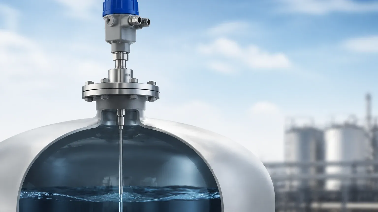
In the landscape of industrial process control, accurate level measurement is fundamental to operational safety, inventory management, and efficiency. Among the various technologies available, the level sensor guided wave radar (GWR) has emerged as a preferred solution for challenging environments where traditional methods like ultrasonic or non-contact radar may struggle. Based on the principle of Time Domain Reflectometry (TDR), GWR offers a contact-based measurement that is largely immune to changes in physical properties such as pressure, temperature, and density.
Understanding the Measurement Principle: Time Domain Reflectometry (TDR)
Guided wave radar technology operates by sending low-power, high-frequency microwave pulses along a dedicated waveguide—the probe. This probe is immersed in the medium being measured. As the pulse travels down the probe, it encounters a change in the dielectric constant (εr) at the surface of the product (liquid or solid).
When the pulse hits the surface, a portion of the energy is reflected back to the transmitter. The electronics within the sensor measure the time-of-flight—the duration between the emission of the pulse and the receipt of the reflection. Since the speed of electromagnetic waves is constant, the distance to the surface is calculated using the formula:
Distance = (Speed of Light × Time-of-Flight) / 2
Because the pulse is physically guided by the probe, the signal remains focused and experiences significantly less attenuation than non-contact radar signals. This makes GWR exceptionally reliable in applications involving low dielectric constants, turbulent surfaces, or narrow tanks with internal obstructions.
Guided Wave Radar vs. Non-Contact Radar: Key Differences
While both technologies utilize radar pulses, their application envelopes differ significantly. Non-contact radar is ideal for corrosive media that might damage a probe or for applications where hygiene requirements forbid contact. However, non-contact radar can be affected by heavy foam, dust, and tank geometry.
In contrast, the level sensor guided wave radar excels because the signal is contained within the immediate vicinity of the probe. This containment allows for:
1. Measurement in Narrow Nozzles: GWR can be installed in small-diameter nozzles where non-contact radar would suffer from signal interference.
2. Foam Penetration: In many cases, GWR pulses can penetrate layers of foam to reach the actual liquid surface, a task that often confuses ultrasonic or non-contact radar sensors.
3. Immunity to Turbulence: Agitators and surface ripples have a minimal impact on the guided pulse compared to the scattered reflections they cause for non-contact sensors.
Selecting the Right Probe Configuration
The performance of a GWR sensor is heavily dependent on the type of probe selected. Welk offers several configurations to match specific process requirements:
1. Single Rod/Cable Probes
Single rod probes are the most versatile and easiest to clean. They are suitable for liquids with high dielectric constants (εr > 10) and are less prone to media buildup. Single cable probes are used for tall silos or tanks, reaching lengths of up to 30 meters (approx. 100 ft).
2. Twin Rod/Cable Probes
Twin probes provide a more concentrated electromagnetic field between the two conductors. This increases the signal strength, making them suitable for media with lower dielectric constants (εr > 1.9). However, they are more susceptible to clogging if the media contains solids or is highly viscous.
3. Coaxial Probes
Coaxial probes consist of a rod inside a perforated outer tube. This design offers the highest signal efficiency because the electromagnetic field is entirely contained within the tube. Coaxial probes are the gold standard for measuring low-dielectric liquids (like oils or liquefied gases) and are unaffected by tank internals or mounting nozzles. They are typically limited to clean, low-viscosity liquids to prevent blockage of the outer tube.
Industrial Applications and Media Compatibility
Guided wave radar is utilized across a broad spectrum of industries due to its robustness.
* Oil and Gas: Measuring crude oil, condensates, and interface levels (e.g., oil over water). GWR is particularly effective at detecting the transition between two liquids with different dielectric constants.
* Chemical Processing: Handling solvents, acids, and bases. With PTFE-coated probes, GWR can withstand highly aggressive chemical environments.
* Water and Wastewater: Monitoring levels in sumps, lift stations, and chemical feed tanks. It is unaffected by the high humidity and steam often present in these environments.
* Power Generation: High-pressure steam drum level measurement. Unlike hydrostatic sensors, GWR is not affected by the density changes of water at high temperatures.
Installation Guidelines for Optimal Performance
To ensure the accuracy of a level sensor guided wave radar, several installation factors must be considered:
* Nozzle Dimensions: The nozzle height should be kept as short as possible. For single rod probes, the nozzle diameter should be at least 50 mm (2 in) to prevent interference, whereas coaxial probes can be mounted in nozzles of nearly any diameter.
* Proximity to Walls: Single and twin probes should be mounted at a distance from the tank wall—typically at least 300 mm (12 in)—to avoid signal interference. Coaxial probes do not have this restriction.
* Obstructions: The probe must not come into contact with agitators, heating coils, or other internal structures. If contact is possible due to fluid movement, the probe should be anchored at the bottom.
* Grounding: Proper grounding of the sensor housing to the metal tank (or a reference ground in plastic tanks) is essential for stable signal processing.
Enhancing System Reliability with Level Switches
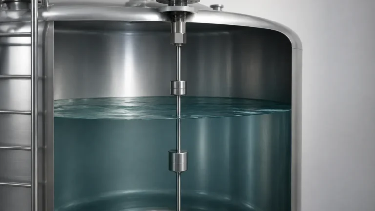
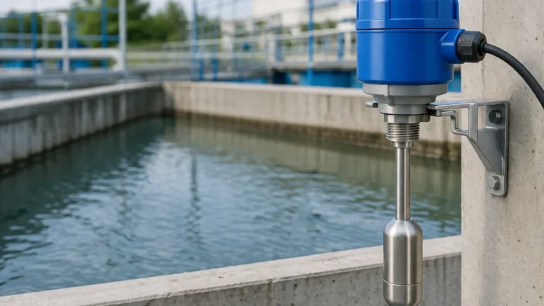
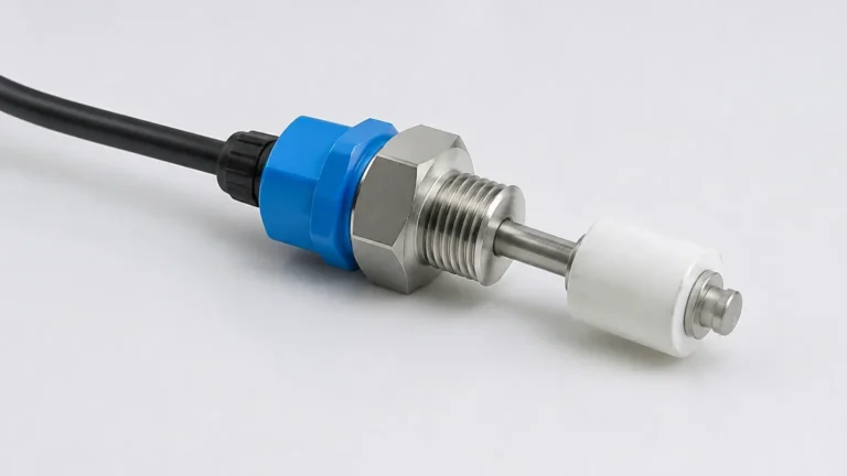
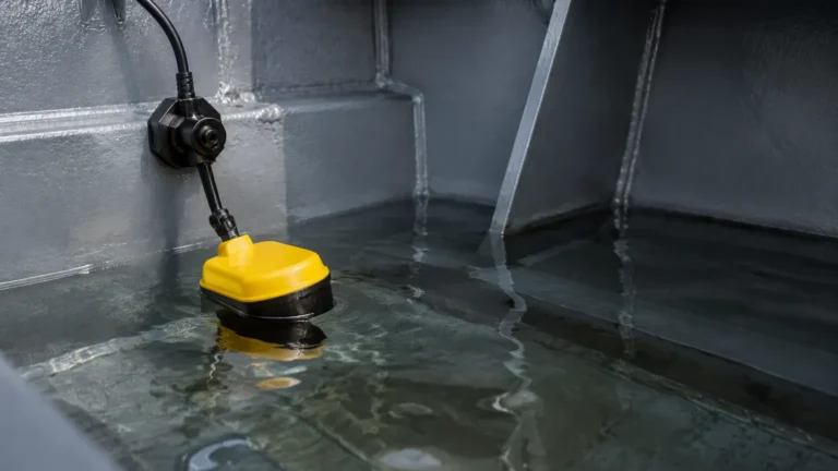
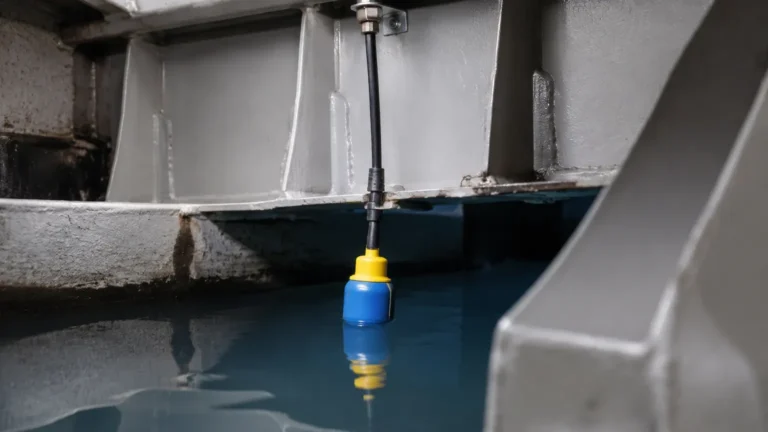
While GWR provides continuous, high-precision level data, industrial safety standards often dictate the use of redundant systems. In critical applications, such as preventing the overfill of a hazardous chemical tank or protecting a pump from running dry, it is standard practice to integrate independent Level Switches.
Point level switches act as a secondary safety layer. While the GWR sensor tracks the level throughout the entire range for process control, the level switch provides a discrete signal (on/off) when a specific threshold is reached. This hardware diversity—combining radar technology with mechanical or vibratory switches—ensures that even if the primary sensor's signal is lost or compromised by extreme buildup, the system can still trigger an emergency shutdown or alarm.
Technical Specifications and Selection Table
When specifying a GWR unit, engineers should refer to the following general parameters to ensure compatibility with the process:
| Feature | Specification Range (Typical) | Notes |
| :— | :— | :— |
| Measuring Range | 0.1 m to 30 m (0.33 ft to 100 ft) | Dependent on probe type (cable vs. rod) |
| Accuracy | ±2 mm to ±5 mm (±0.08 in to ±0.2 in) | Higher accuracy with coaxial probes |
| Process Temperature | -50°C to +400°C (-58°F to +752°F) | Requires high-temp spacers/seals |
| Process Pressure | Vacuum to 400 bar (5800 psi) | High-pressure ceramic seals available |
| Dielectric Constant | εr ≥ 1.4 | Lower values require coaxial probes |
| Output Signal | 4-20mA HART, RS485, Modbus | Digital integration for automation |
Limitations and Maintenance Considerations
Despite its versatility, GWR is not a "one-size-fits-all" solution. Engineers must be aware of its limitations:
1. Probe Buildup: While GWR can handle some coating, excessive buildup of conductive or thick, viscous material can attenuate the signal or cause "ghost" reflections. In such cases, regular cleaning or the use of PTFE-coated probes is necessary.
2. Mechanical Stress: In solid applications (like grain or sand), the downward pull (tensile load) on a cable probe can be immense. The tank roof and the probe itself must be rated for these mechanical forces.
3. Dead Zones: Every GWR sensor has an "Upper Blocking Distance" (Upper Null Zone) and a "Lower Blocking Distance." Measurement is not possible in these zones, usually the top 100-300 mm (4-12 in) of the probe. This must be accounted for during tank design.
Frequently Asked Questions (FAQ)
Q: Can guided wave radar measure the interface between two liquids?
A: Yes. GWR is excellent for interface measurement (e.g., oil over water). The pulse reflects off the upper liquid (low dielectric) and continues through it to reflect off the lower liquid (high dielectric). The upper layer must have a lower dielectric constant than the lower layer, and the layer must be at least 50-100 mm (2-4 in) thick for the sensor to distinguish the two reflections.
Q: Does the tank material affect the GWR measurement?
A: For coaxial probes, the tank material is irrelevant. For single rod or cable probes, if the tank is non-metallic (plastic or fiberglass), a metal flange or a special grounding plate must be used at the mounting point to provide a reference for the radar pulse.
Q: How does GWR handle vacuum conditions?
A: Unlike ultrasonic sensors, which require a medium (air) to transmit sound, radar pulses travel through a vacuum without any loss of speed or accuracy. This makes GWR ideal for vacuum distillation columns and similar vessels.
Q: Is it possible to cut the probe to length in the field?
A: Most rod and cable probes from manufacturers like Welk are field-adjustable. After cutting the probe, the user must update the probe length in the sensor software to maintain accuracy. Coaxial probes are generally more difficult to modify in the field and should be ordered to the correct length.
Conclusion
The level sensor guided wave radar represents a pinnacle of reliability in contact-based level measurement. By guiding the microwave pulse directly to the target, it overcomes the traditional hurdles of signal scattering and environmental interference. When properly specified with the correct probe type and complemented by independent Level Switches for safety redundancy, GWR provides a robust foundation for modern industrial automation and process safety.