Gauges Levels
Gauges Levels
In industrial process engineering, the ability to accurately monitor and verify liquid levels is fundamental to safety, efficiency, and inventory management. While modern automation relies heavily on electronic transmitters, the use of physical gauges for levels provides a critical layer of local visualization and fail-safe redundancy. Among the various technologies available, Magnetic & Local Level Gauges stand out as the primary choice for high-pressure, corrosive, or hazardous applications where direct contact with the process fluid must be managed carefully.
This guide explores the engineering principles, selection criteria, and installation requirements for local level measurement instruments, focusing on how to choose the right technology for specific industrial environments.
Principles of Operation for Local Level Gauges
Before selecting an instrument, it is essential to understand the physics behind how these devices track fluid height. Local level gauges generally fall into two categories: direct-view glass gauges and magnetic bypass gauges.
The Buoyancy and Magnetic Coupling Principle
Magnetic level gauges operate on the principle of buoyancy and magnetic attraction. A float, specifically engineered to match the specific gravity (SG) of the process liquid, is placed inside a bypass chamber (a vertical pipe connected to the side of the tank). Inside this float is a high-intensity permanent magnet.
As the liquid level in the tank rises or falls, the float moves accordingly within the chamber. Outside the chamber, an indicator rail is mounted. This rail contains a series of bi-color magnetic flaps or rollers (usually red and white). As the float passes these flaps, the magnetic field causes them to rotate 180 degrees, changing their color. This creates a clear, high-contrast visual representation of the liquid level without the fluid ever leaving the containment of the pressure-rated chamber.
Direct Visual Principles (Reflex and Transparent)
Direct-view gauges use toughened glass to allow operators to see the actual liquid.
- Reflex Gauges: Use the principle of light refraction. The glass has prismatic grooves. In the area filled with gas/vapor, light is reflected, appearing bright white. In the area filled with liquid, light is absorbed, appearing dark black.
- Transparent Gauges: Use two pieces of clear glass on opposite sides of the chamber. This allows light to pass through the fluid, which is necessary for observing the color of the liquid or identifying the interface between two different liquids.
Types of Gauges for Monitoring Levels
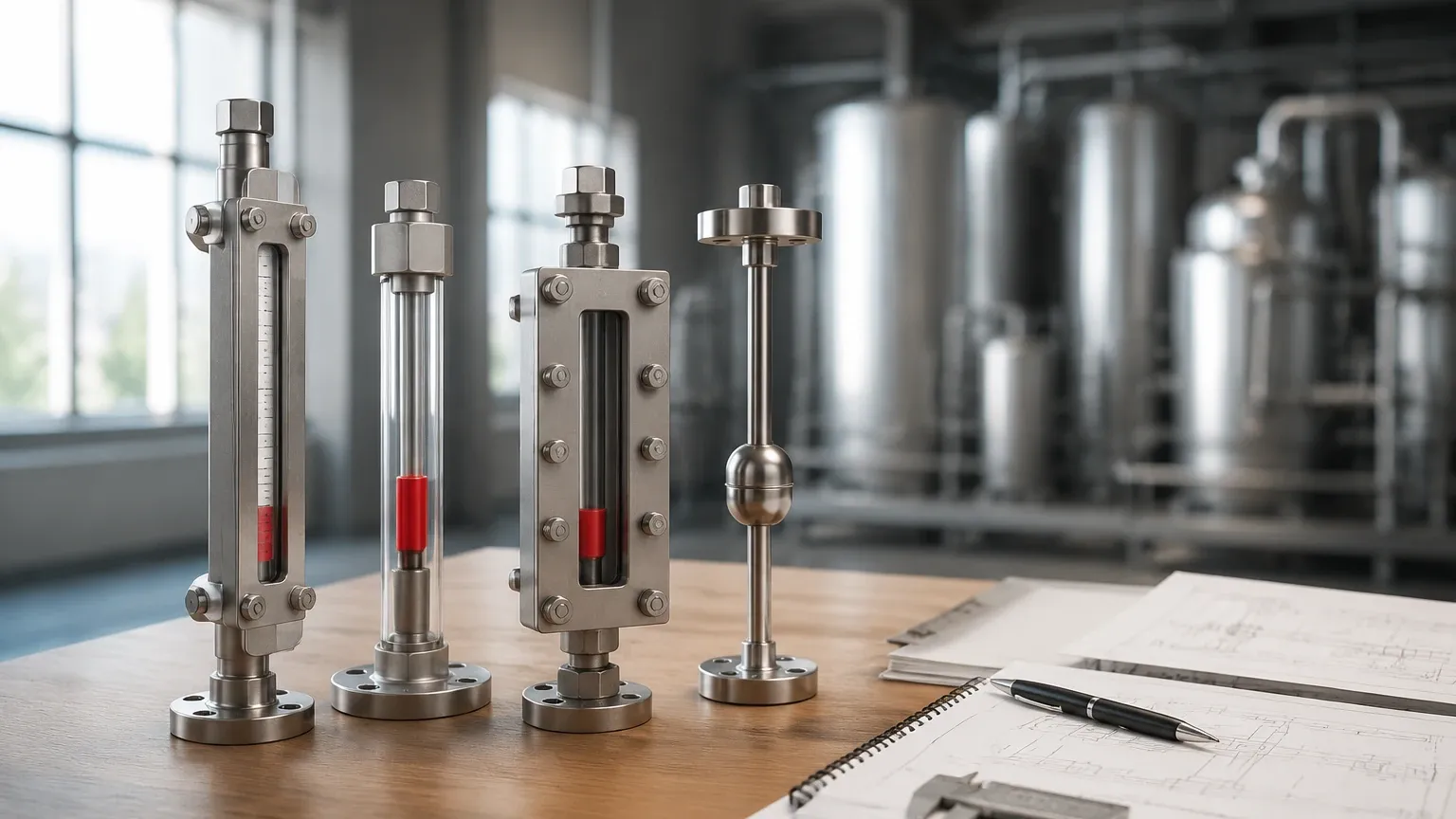
Choosing the correct instrument depends on the chemical properties of the fluid, the operating pressure, and the required visibility distance. The following table summarizes the primary types used in modern industrial automation.
Comparative Selection Table
| Gauge Type | Max Pressure (Typical) | Max Temperature | Visibility | Best Application |
| :— | :— | :— | :— | :— |
| Magnetic Level Gauge | Up to 250 bar (25 MPa) | -196°C to 450°C | Excellent (up to 30m) | Hazardous, toxic, or high-pressure fluids. |
| Reflex Glass Gauge | Up to 40 bar (4 MPa) | Up to 400°C | Good | Clean, non-viscous liquids; steam applications. |
| Transparent Glass Gauge | Up to 250 bar (25 MPa) | Up to 400°C | Moderate | Interface measurement; colored or corrosive fluids. |
| Tubular Glass Gauge | Low Pressure (<10 bar) | <150°C | High | Non-hazardous water tanks; atmospheric storage. |
| Magnetic Top-Mounted | Up to 40 bar (4 MPa) | Up to 200°C | Excellent | Underground tanks or sumps where side access is impossible. |
Key Engineering Selection Criteria
When specifying gauges levels for a project, several technical parameters must be confirmed to ensure the longevity and accuracy of the device.
1. Fluid Density and Specific Gravity (SG)
For magnetic gauges, the float is the most critical component. It must be light enough to float on the liquid but strong enough to withstand the process pressure. If the SG of the liquid changes (due to temperature fluctuations), the float's immersion depth will change, leading to measurement errors. Engineers must specify the minimum and operating SG during the design phase.
2. Pressure and Temperature Ratings
Industrial tanks often operate under extreme conditions. While glass gauges are limited by the mechanical strength of the glass and gaskets, magnetic level gauges can be manufactured from various alloys (316L Stainless Steel, Titanium, Hastelloy) to handle pressures exceeding 200 bar (20 MPa). For cryogenic applications, such as LNG, specialized frost-proof acrylic blocks are added to the indicator to prevent ice buildup from obscuring the view.
3. Material Compatibility
The wetted parts must be chemically compatible with the process media.
- Stainless Steel (316/316L): Standard for water, oils, and mild chemicals.
- PTFE/PFA Lining: Required for highly corrosive acids like hydrochloric or sulfuric acid.
- Titanium: Used for seawater or high-temperature corrosive environments.
4. Visibility and Remote Transmission
In large-scale plants, a local gauge is often paired with a reed chain transmitter or a magnetostrictive sensor. This allows the Magnetic & Local Level Gauges to provide both a local visual reading for technicians and a 4-20mA or HART signal for the control room (PLC/DCS).
Installation and Maintenance Considerations
Proper installation is vital for the safety and accuracy of the instrument. Because these devices rely on physical movement (floats) or light paths (glass), specific geometric constraints apply.
Mounting Configurations
The most common installation is the "Side-Side" configuration, where the gauge is connected to the tank via two nozzles. For tanks located below ground, a "Top-Mounted" gauge is used, utilizing a float connected to a rod that moves the magnet within a sealed column above the tank.
Essential Installation Steps:
1. Vertical Alignment: The gauge chamber must be installed perfectly vertical. Even a slight tilt can cause the float to rub against the chamber walls, leading to sticking or mechanical wear.
2. Isolation Valves: Always install high-quality isolation valves (ball or needle valves) between the tank and the gauge. This allows for maintenance or glass replacement without draining the entire vessel.
3. Venting and Draining: Every gauge should be equipped with a vent plug at the top and a drain valve at the bottom. This is necessary for clearing debris and safely de-pressurizing the unit before service.
4. Magnetic Interference: Ensure that no large ferrous structures or high-voltage cables are located within 100mm to 200mm of a magnetic level gauge, as these can interfere with the float's magnetic field and cause false readings.
Limitations and Safety Risks
While highly reliable, gauges for levels are not universal solutions. Engineers must be aware of the following limitations:
* Viscosity and Coating: Highly viscous liquids or those that crystallize can impede the movement of the float in magnetic gauges or obscure the glass in reflex gauges. In such cases, internal heating jackets (steam or electric) may be required to maintain fluid mobility.
* Magnetic Particles: If the process fluid contains iron filings or magnetic scale, these particles will cling to the internal magnet in the float. Over time, this increases the float's weight and can eventually jam it. Magnetic filters (traps) should be installed in the bypass line if magnetic debris is expected.
* Glass Fragility: In direct-view gauges, the glass is a potential point of failure. Thermal shock (sudden temperature changes) can cause the glass to crack. For high-pressure steam, mica shields must be used to protect the glass from erosion.
Frequently Asked Questions (FAQs)
Q: Can a magnetic level gauge be used for interface measurement?
A: Yes. By weighting the float to a specific density that sits between the SG of the two liquids (e.g., oil and water), the gauge will accurately indicate the level of the interface.
Q: How often should a level gauge be calibrated?
A: Unlike electronic sensors, mechanical gauges do not drift. However, they should be inspected annually for float wear, sediment buildup in the chamber, and the integrity of the gaskets/seals.
Q: What is the "Dead Zone" in a level gauge?
A: The dead zone refers to the areas at the very top and bottom of the gauge where the float cannot travel or where the magnetic flaps cannot be actuated. When designing a tank, the nozzle positions must account for these zones to ensure the critical operating range is visible.
Q: Are these gauges suitable for food and beverage applications?
A: Yes, provided they are manufactured with sanitary fittings (Tri-clamp) and polished stainless steel surfaces (Ra < 0.8 µm) to prevent bacterial growth.
Conclusion
Selecting the appropriate gauges levels involves a balance between process safety, visibility requirements, and budget. For most modern industrial applications, the magnetic level gauge offers the highest safety profile by eliminating the risk of glass breakage and providing a clear, long-distance visual of the tank status. By following strict installation guidelines and ensuring material compatibility, these instruments provide decades of reliable service in the most demanding environments. For specific project requirements, consulting with a manufacturer like Welk ensures that the float design and chamber materials are optimized for your unique process conditions.