Gauge K
Gauge K
In the landscape of industrial process control, the visual verification of liquid levels remains a critical safety and operational requirement. While digital transmitters provide data to control rooms, local indicators provide the "ground truth" for field operators. The Gauge K series represents a specialized category of Magnetic & Local Level Gauges designed to bridge the gap between high-pressure durability and clear, maintenance-free visibility. This guide explores the technical foundations, selection criteria, and engineering best practices for implementing Gauge K solutions in demanding industrial environments.
Understanding the Role of Gauge K in Industrial Level Measurement
Local level gauges are categorized by their method of display and their pressure boundary integrity. Traditional tubular glass gauges or reflex glass gauges, while common, present inherent risks regarding glass breakage and seal leakage, especially when handling hazardous or high-pressure media. The Gauge K configuration addresses these vulnerabilities by utilizing a magnetic coupling principle that completely isolates the process fluid from the viewing area.
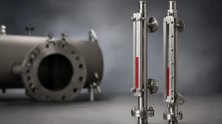
As part of the broader family of Magnetic & Local Level Gauges, the Gauge K is typically employed in bypass installations. It consists of a vertical chamber connected to a vessel via two nozzles (process connections). Because the chamber is a sealed metal tube, it provides the same pressure rating as the vessel itself, effectively eliminating the "weak link" often associated with sight glasses.
Key Industrial Applications
* Oil and Gas: Separators, storage tanks, and flare knock-out drums where high pressures and volatile fluids are standard.
* Chemical Processing: Handling of corrosive acids, bases, and solvents where leakage poses significant environmental and safety risks.
* Power Generation: Boiler feedwater systems and condensate tanks requiring high-temperature resilience.
* Water Treatment: Large-scale storage tanks where long-term reliability and low maintenance are prioritized.
Operating Principles of Magnetic & Local Level Gauges
The Gauge K operates on two fundamental physical principles: Archimedes' Principle (buoyancy) and Magnetism.
1. The Float and Chamber System
Inside the non-magnetic metal chamber (usually stainless steel), a float is designed with a specific density to match the process fluid. This float contains a high-intensity 360° magnetic ring. As the liquid level in the vessel rises or falls, the liquid level in the bypass chamber moves in tandem, causing the float to track the level precisely.
2. The Magnetic Coupling
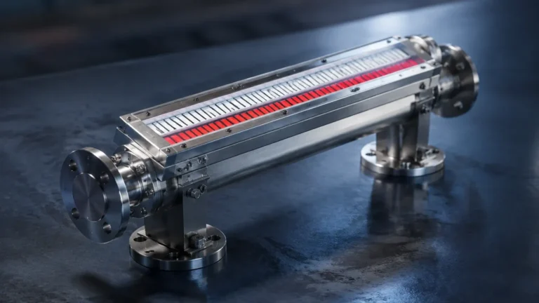
Mounted on the outside of the chamber is the indicator rail. This rail contains a series of bi-color magnetic flaps or rollers (often red and white). As the float moves past these flaps, the magnetic field causes them to rotate 180°. Flaps below the float turn red (representing liquid), while those above the float remain white (representing gas or vapor).
This magnetic coupling ensures that there is no physical connection between the process fluid and the atmosphere. If the indicator rail is damaged or removed, the pressure boundary remains intact, preventing any potential for a catastrophic leak.
Technical Specifications and Performance Parameters
When specifying a Gauge K system, engineers must evaluate the mechanical limits of the chamber and the buoyancy limits of the float. The following table outlines the typical technical boundaries for standard and reinforced Gauge K configurations.
Gauge K Specification Table
| Parameter | Standard Configuration | High-Pressure / High-Temp Variant |
| :— | :— | :— |
| Chamber Material | SS304 / SS316L | Hastelloy C / Monel / Titanium |
| Pressure Rating | PN16 to PN64 (1.6 – 6.4 MPa) | Up to PN400 (40 MPa) |
| Temperature Range | -40°C to +250°C | -196°C to +450°C |
| Specific Gravity | 0.5 to 2.0 g/cm³ | Custom floats for < 0.4 g/cm³ |
| Center-to-Center | 300 mm to 6,000 mm | Custom lengths up to 15,000 mm |
| Connection Size | DN15 to DN50 (1/2" to 2") | Custom Flanged or NPT/BSP Threaded |
Float Engineering
The float is the most critical component of the Gauge K. It must be engineered to withstand the full collapse pressure of the system while remaining light enough to float in the process medium. For high-pressure applications, the float is often pressurized with inert gas to prevent deformation, or manufactured from high-strength titanium alloys.
Selection Criteria: Choosing the Right Gauge K Configuration
Selecting the appropriate Gauge K requires a detailed understanding of the process conditions. Failure to account for specific gravity or fluid viscosity can lead to inaccurate readings or float sticking.
1. Fluid Compatibility and Specific Gravity
The float must be lighter than the liquid it is measuring. In applications involving liquefied gases (like LPG or LNG) with very low specific gravities (e.g., 0.45 g/cm³), a specialized long-format float is required to provide enough buoyant force to flip the indicator flaps.
2. Viscosity and Solid Content
While Magnetic & Local Level Gauges are more robust than glass gauges, extremely viscous fluids (above 500 cSt) can impede float movement. Similarly, fluids with high particulate content or magnetic particles (like magnetite in boiler water) require the installation of magnetic filters or traps to prevent interference with the float's magnetic field.
3. Indicator Visibility and Environment
For outdoor installations in harsh environments, the indicator rail should be UV-stabilized and IP67 or IP68 rated. In areas with significant vibration, "damped" flaps are recommended to prevent accidental flipping caused by mechanical shock rather than level changes.
Installation Guidelines and Best Practices
Correct installation is paramount to ensure the longevity and accuracy of the Gauge K. As a bypass instrument, it relies on the principle of communicating vessels.
Orientation and Alignment
The chamber must be installed perfectly vertical. Even a slight tilt (greater than 3 degrees) can cause the float to rub against the chamber walls, leading to friction and eventual sticking. Use a spirit level or transit during the welding or bolting process to ensure verticality.
Magnetic Interference
Because the system relies on magnetic coupling, it must be kept away from large ferrous structures or high-voltage cables that generate electromagnetic fields. A minimum clearance of 100 mm from other carbon steel pipes or supports is generally recommended.
Venting and Draining
Every Gauge K installation should include a vent valve at the top and a drain valve at the bottom. This allows for:
1. Commissioning: Slowly filling the chamber to avoid "slugging" the float against the top of the chamber.
2. Maintenance: Flushing out accumulated sediment or scale that might settle at the bottom of the chamber.
Insulation and Heat Tracing
In applications where the process fluid must be kept at a specific temperature to maintain fluidity (e.g., liquid sulfur or heavy crude), the Gauge K can be equipped with a heating jacket or electric heat tracing. However, ensure that the insulation does not cover the indicator rail, as the flaps need to remain visible and the magnets must stay below their Curie temperature to maintain magnetic strength.
Maintenance, Troubleshooting, and Operational Safety
One of the primary advantages of the Gauge K series is its low maintenance requirement. Unlike glass gauges, there are no seals to retorque and no glass to clean. However, periodic inspections are still necessary.
Common Troubleshooting Scenarios
* Indicator Stays Stationary: This usually indicates a stuck float. Check for sediment at the bottom of the chamber or verify if the process fluid's specific gravity has changed significantly. Use an external magnet to manually move the float and check for freedom of movement.
* Erratic Flap Movement: This may be caused by rapid boiling or turbulence within the chamber. Installing a "stilling well" or a smaller diameter orifice in the process connections can help dampen the turbulence.
* Faded Indicator Flaps: In high-UV environments, standard plastic flaps may fade. Upgrade to ceramic or powder-coated aluminum flaps for better long-term legibility.
Enhancing Functionality with Transmitters
While the Gauge K is a local indicator, it can be easily upgraded to provide remote signals. By strapping a magnetostrictive transmitter or a reed-chain sensor to the outside of the chamber, the system provides a 4-20mA HART or Modbus signal to the PLC/DCS. This provides a dual-redundant system: a mechanical local display and an electronic remote signal, both driven by the same magnetic float.
Conclusion
The Gauge K offers a robust, safe, and highly visible solution for local level monitoring in complex industrial environments. By eliminating the risks associated with pressurized glass and providing a clear, magnetic-based interface, it ensures that operators have reliable data where they need it most—at the tank side. When selecting a system from the range of Magnetic & Local Level Gauges, careful consideration of specific gravity, material compatibility, and installation environment will ensure a service life that often exceeds that of the vessel itself.
Frequently Asked Questions (FAQs)
Q: Can Gauge K be used for interface measurement between two liquids?
A: Yes. By weighting the float to a specific density that is between the densities of the two liquids (e.g., between oil and water), the float will sink through the upper layer and float on the lower layer, indicating the interface level.
Q: What is the maximum length for a single-piece Gauge K?
A: Standard chambers are usually manufactured up to 6 meters. For taller vessels, the chambers can be manufactured in sections and joined with flanges, though careful alignment is required to ensure smooth float transition between sections.
Q: How do I clean the inside of the chamber?
A: The chamber should be isolated using the process valves, drained, and then flushed through the vent/drain ports. If heavy scaling is present, the bottom flange can be removed to extract the float and allow for mechanical cleaning of the tube interior.