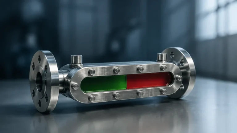
Marking Gauge Level
Marking Gauge Level
In industrial process control, the ability to verify liquid levels at the point of measurement remains a critical safety and operational requirement. While digital transmitters provide data to control rooms, the marking gauge level—the visual interface on a local indicator—serves as the primary manual verification tool for field operators. Whether through magnetic flags, glass tubes, or mechanical scales, local level gauges provide a fail-safe reference that does not depend on electrical power.
Selecting the correct Magnetic & Local Level Gauges requires an understanding of how these markings are generated and maintained across different pressure, temperature, and chemical environments. This guide explores the engineering principles, selection criteria, and installation best practices for achieving accurate local level marking in industrial applications.
Principles of Local Level Measurement
To understand the marking gauge level, one must first understand the mechanical principles that drive the visual indicator. Local level gauges typically operate on one of three fundamental physical concepts: buoyancy, differential pressure, or direct visual access.
The Buoyancy and Magnetic Coupling Principle
Magnetic level gauges are the most common solution for high-pressure or hazardous fluids. They consist of a non-magnetic chamber (usually stainless steel) connected to the process vessel. Inside this chamber, a float containing a permanent magnet assembly rises and falls with the liquid level.
Outside the chamber, a visual indicator—the marking gauge—is mounted. This indicator contains a series of bi-color magnetic flaps or a follower. As the float moves, the magnetic field couples with the flaps, rotating them 180 degrees to change their color (typically from white to red). The boundary between the two colors represents the marking gauge level. Because the fluid is completely contained within the pressure-sealed chamber, there is no risk of leaks associated with glass breakage.
Direct Sight Principles
Traditional sight glasses allow the operator to see the actual liquid through a transparent tube or window. The "marking gauge" in this instance is often a scale plate mounted adjacent to the glass. While simple, these are limited by the physical strength of the glass and the potential for the fluid to coat or stain the viewing area, obscuring the marking gauge level over time.
Understanding the Marking Gauge Level System
The "marking" component of a level gauge is not merely a sticker or a painted line; it is a precision-engineered scale system designed for readability and durability.
Indicator Types and Visibility
1. Magnetic Flaps (Rollers): These provide high visibility from a distance. The width of the flaps and the contrast of the colors are designed so that an operator can identify the marking gauge level from 20 to 30 meters away.
2. Shuttle/Follower Indicators: A single brightly colored point that moves along a scale. These are often used when a continuous color change is not required or in high-vibration environments where flaps might inadvertently flip.
3. Engraved Scales: For precise engineering measurements, scales are typically manufactured from stainless steel or aluminum and engraved with metric (mm/cm) or imperial (inches/feet) units. These are mounted parallel to the indicator tube.
Calibration and Specific Gravity
The accuracy of the marking gauge level is heavily dependent on the float's buoyancy. Since the float must be weighted to sit exactly at the liquid-to-vapor interface, the specific gravity (SG) of the process fluid is a critical variable. If the fluid density changes due to temperature fluctuations, the float may sit higher or lower, leading to a discrepancy between the actual level and the marking gauge level.
Comparison of Local Level Gauge Technologies
When selecting a system for marking gauge level monitoring, engineers must weigh the pros and cons of different technologies based on the application's physical constraints.
| Feature | Magnetic Level Gauges | Reflex Glass Gauges | Transparent Glass Gauges |
| :— | :— | :— | :— |
| Visibility | Excellent (High contrast flaps) | Good (Prismatic effect) | Moderate (Requires backlight) |
| Pressure Range | Up to 400 bar | Up to 250 bar | Up to 250 bar |
| Temperature Range | -196°C to +450°C | Up to 400°C | Up to 400°C |
| Hazardous Fluids | Highly Recommended | Limited | Limited |
| Maintenance | Low (No glass to clean) | Moderate (Glass cleaning) | High (Gasket/Glass wear) |
| Scale Type | External Metal Scale | Integrated or External | External |
Technical Selection Criteria for Marking Gauge Level Systems
Choosing the right equipment to display the marking gauge level involves more than just picking a height. The following factors must be confirmed during the engineering phase:
1. Material Compatibility
The chamber, float, and gaskets must be compatible with the process media. For corrosive chemicals, 316L stainless steel is standard, but specialized alloys like Hastelloy, Monel, or plastic linings (PTFE/PP) may be required. The marking gauge scale itself should be weather-resistant, typically using 304 or 316 stainless steel to prevent corrosion from salt spray or industrial fumes.
2. Pressure and Temperature Ratings
As temperature increases, the structural integrity of the chamber and the magnetic strength of the float's internal magnets may decrease. High-temperature applications require specialized insulation for the indicator to protect the marking gauge level components (like the plastic or aluminum flaps) from warping or losing their magnetic properties.
3. Center-to-Center (C-C) Distance
This is the distance between the top and bottom process connections. The marking gauge level scale must cover the entire C-C range to ensure there are no "blind spots" where the liquid level is unknown. Standard C-C distances range from 300 mm to over 6000 mm, though longer gauges often require intermediate supports.

Installation and Maintenance Guidelines
Proper installation is paramount to ensuring the marking gauge level reflects the true state of the vessel.
Installation Considerations
* Vertical Alignment: The gauge must be installed perfectly vertical. Even a slight tilt can cause the float to rub against the chamber walls, leading to friction that prevents the float from tracking the liquid level accurately.
* Magnetic Interference: Because the system relies on magnetic coupling, the gauge should be kept away from large ferrous structures or high-voltage cables that could create electromagnetic fields, which might disrupt the marking gauge level indication.
* Isolation Valves: It is highly recommended to install isolation valves between the vessel and the gauge. This allows for maintenance or cleaning of the chamber without shutting down the entire process.
Maintenance and Cleaning
While magnetic gauges are largely maintenance-free, the chamber should be flushed periodically if the process fluid contains solids or tends to crystallize. If the marking gauge level becomes sluggish, it usually indicates a buildup of sediment at the bottom of the chamber, which can be cleared through the drain plug.
Limitations and Safety Considerations
Despite their reliability, local level gauges have specific boundaries:
* Viscosity Limits: Highly viscous liquids can impede float movement. Generally, if a fluid does not flow easily, a magnetic level gauge may not be the appropriate choice for marking gauge level monitoring.
* Specific Gravity Minimums: If the liquid is too light (e.g., certain liquefied gases with SG < 0.4), it may be difficult to design a float that is both light enough to float and strong enough to withstand the process pressure.
* Coating and Scaling: In glass-based gauges, fluids that leave a film on the glass will eventually make the marking gauge level impossible to read, necessitating frequent teardowns and cleaning.
Frequently Asked Questions (FAQs)
Q: Can I use a magnetic level gauge for interface measurement?
A: Yes. By weighting the float to a specific density that is between the densities of the two liquids (e.g., oil and water), the marking gauge level will indicate the position of the interface rather than the total liquid level.
Q: What happens if the float is installed upside down?
A: The gauge will not function. The magnets inside the float are oriented to align with the indicator flaps. Most floats are clearly marked with "TOP" or an arrow to prevent this common installation error.
Q: How do I verify the marking gauge level is accurate without draining the tank?
A: You can use an external reference magnet. By sliding a strong magnet along the outside of the indicator, you can manually flip the flaps. If the flaps flip back to their original position once the float is reached, the coupling is intact.
Q: Are there limits to the length of the marking gauge?
A: Yes. For very tall tanks (over 6 meters), gauges are often manufactured in sections or require additional support brackets to prevent oscillation and mechanical stress on the process connections.
Conclusion
The marking gauge level remains a cornerstone of industrial safety, providing a clear, mechanical confirmation of tank contents. By selecting high-quality Magnetic & Local Level Gauges and adhering to strict installation standards, facilities can ensure that their operators always have a reliable visual reference, even in the event of a total power failure. When specifying these instruments, always prioritize material compatibility and the specific gravity of the media to ensure the long-term accuracy of the visual marking.