M L Gauge
M L Gauge
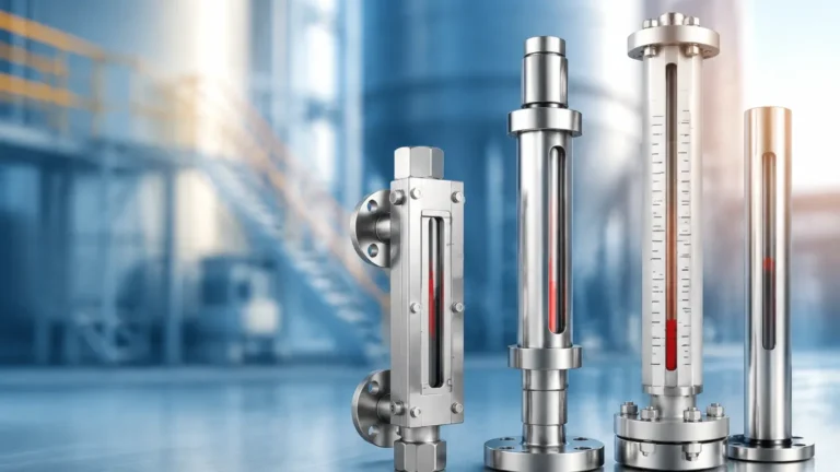
In industrial process control, the term "m l gauge" is frequently used as a professional shorthand for magnetic level gauges. These instruments serve as a primary method for local level indication, providing a clear, high-visibility representation of liquid levels within a vessel without the risks associated with traditional glass sight gauges. As industries move toward higher safety standards and automated monitoring, understanding the engineering principles, selection criteria, and installation requirements of Magnetic & Local Level Gauges is essential for plant engineers and maintenance professionals.
Measurement Principles of Magnetic Level Gauges
The operation of an m l gauge relies on two fundamental physical principles: buoyancy and magnetism. Unlike a standard sight glass where the process fluid is viewed directly through a transparent tube, a magnetic level gauge isolates the fluid within a robust, pressure-retaining chamber.
The Buoyancy Component
Inside the vertical chamber, a specially engineered float is designed to match the specific gravity of the process liquid. As the liquid level rises or falls within the vessel, the float moves accordingly. This float contains a high-intensity omnidirectional magnet assembly. Because the float is sealed and buoyant, it remains at the surface of the liquid (or the interface between two liquids), ensuring that the magnetic field is always aligned with the actual liquid level.
The Magnetic Coupling
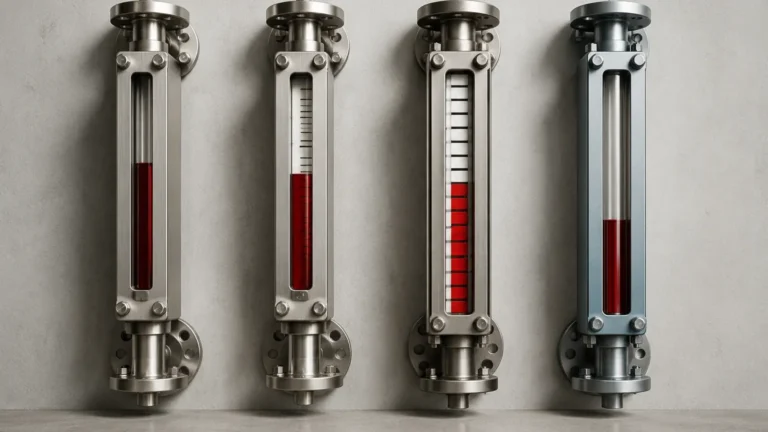
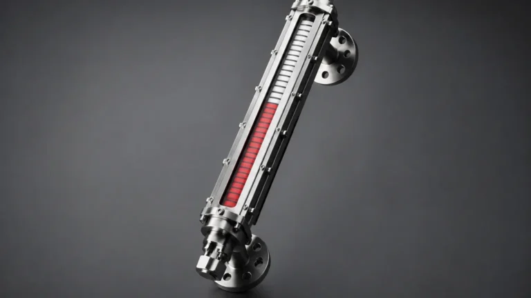
Mounted to the outside of the chamber is an indication rail, which is completely isolated from the process environment. This rail contains a series of bi-color magnetic flags or rollers (typically red and white or yellow and black). As the float moves past these flags, the magnetic field causes them to rotate 180 degrees. This change in orientation creates a distinct color transition that is easily visible from a distance, even in low-light conditions. Because the coupling is magnetic, there is no physical connection between the process fluid and the indicator, eliminating the risk of leaks or glass breakage.
Key Evaluation Criteria for M L Gauge Selection
Selecting the correct m l gauge requires a thorough analysis of the process medium and the environmental conditions. Because these gauges are often used in critical safety applications, the following criteria must be confirmed during the engineering phase.
Material Compatibility
The chamber and float must be resistant to the chemical properties of the fluid. Common materials include:
* Stainless Steel (304/316L): The standard for water treatment and general industrial use.
* Specialty Alloys (Hastelloy, Monel, Titanium): Used for highly corrosive acids or seawater applications.
* Plastics (PP, PVC, PVDF): Suitable for low-pressure corrosive chemical storage.
* PTFE/PFA Lining: Combines the pressure resistance of stainless steel with the chemical inertness of fluoropolymers.
Process Temperature and Pressure
Magnetic level gauges are preferred over sight glasses in high-pressure environments because the metal chamber can be manufactured to meet various pressure vessel codes (such as ASME B31.3). Standard models often handle up to 40 bar (approx. 580 psi), while high-pressure variants can exceed 200 bar. Temperature is equally critical, as extreme heat can affect the magnetic properties of the float (the Curie point) or cause the flags to warp. High-temperature designs utilize insulation jackets and specialized magnetic materials.
Specific Gravity
The float must be precisely weighted to the specific gravity (SG) of the liquid. If the liquid is too light (low SG), a standard float may sink; if it is too heavy, the float may sit too high, leading to measurement errors. For interface applications—where the gauge measures the boundary between two immiscible liquids like oil and water—the float must be calibrated to sink in the upper liquid and float on the lower liquid.
Practical Selection Table
| Application Type | Recommended Material | Pressure Range | Temperature Range | Key Feature |
| :— | :— | :— | :— | :— |
| Water Treatment | 304 Stainless Steel | Up to 16 bar | -20°C to 100°C | Cost-effective, durable |
| Chemical Processing | 316L or PTFE Lined | Up to 40 bar | -40°C to 200°C | Corrosion resistance |
| Oil & Gas (High Pressure) | Heavy-wall 316/316L | Up to 250 bar | -50°C to 450°C | High-strength chamber |
| Acid Storage | PVC or PP | Up to 6 bar | 0°C to 60°C | Non-metallic construction |
| Cryogenic Fluids | Insulated Stainless Steel | Up to 25 bar | Down to -196°C | Vacuum jacketed chamber |
Installation Considerations
Proper installation is vital for the longevity and accuracy of an m l gauge. Since the device relies on a free-moving float, any mechanical obstruction or misalignment can cause the gauge to fail.
1. Vertical Alignment: The chamber must be installed perfectly vertical. Even a slight tilt can cause the float to rub against the chamber walls, leading to friction that prevents smooth movement or causes the float to stick.
2. Magnetic Interference: Because the device operates on magnetic coupling, it must be kept away from large ferrous structures or high-voltage cables that generate electromagnetic fields. Standard practice suggests a minimum clearance of 100mm (approx. 4 inches) from steel supports.
3. Isolation Valves: It is highly recommended to install isolation valves (ball or gate valves) between the vessel and the gauge. This allows for maintenance and float inspection without draining the entire process tank.
4. Vent and Drain Plugs: Every m l gauge should be equipped with a vent at the top and a drain at the bottom. This facilitates cleaning of the chamber and ensures that no gas pockets interfere with the liquid level.
Integration with Automation
While the primary function of an m l gauge is local visual indication, modern industrial requirements often demand remote monitoring. To bridge this gap, Magnetic & Local Level Gauges can be equipped with secondary transmitters and switches.
* Reed Chain Transmitters: A series of reed switches and resistors mounted in a tube alongside the chamber. The float's magnet triggers these switches, providing a 4-20mA signal proportional to the level.
* Magnetostrictive Transmitters: These offer higher precision (up to +/- 1mm) and are ideal for custody transfer or high-accuracy inventory management.
* Level Switches: Magnetic bistable switches can be clamped to the chamber at specific points to trigger high or low-level alarms. These are often used for pump control or emergency shutdown (ESD) systems.
Limitations and Risks
Despite their versatility, m l gauges are not suitable for every application. Understanding these limitations prevents costly misapplications.
* Viscous and Dirty Liquids: If a liquid is highly viscous or contains significant suspended solids, the float may become stuck or the chamber may clog. In such cases, regular flushing via the drain port is required, or an alternative technology like a radar level meter may be more appropriate.
* Magnetic Particles: If the process fluid contains iron filings or magnetic scales, these particles will adhere to the float's magnet, eventually increasing its weight and causing it to sink or jam.
* Flash Vapors: In applications with boiling liquids, rapid flashing can cause the float to bounce violently, potentially damaging the internal stops or the float itself.
Maintenance and Troubleshooting
Maintenance for a magnetic level gauge is generally minimal compared to sight glasses, which require frequent cleaning and seal replacements. However, a routine inspection schedule should include:
* Flushing the Chamber: Periodically open the drain valve to remove any accumulated sediment.
* Float Inspection: Once a year, or during plant shutdowns, remove the float to check for signs of corrosion, pitting, or collapsed walls (due to pressure spikes).
* Indicator Check: Ensure the flags move freely. If flags are stuck due to environmental buildup (dust or salt spray), the indicator rail should be cleaned or replaced.
Frequently Asked Questions (FAQs)
Q: Can an m l gauge be used for underground tanks?
A: Yes, but it requires a "top-mount" configuration. In this design, a float on the liquid surface is connected via a rod to a magnet in an upper chamber, which then actuates the external indicator.
Q: What happens if the float is installed upside down?
A: The gauge will not function correctly. Most floats are weighted and have the magnet assembly positioned at a specific point relative to the fluid surface. Floats are typically marked with a "TOP" arrow to prevent installation errors.
Q: How do I choose between a magnetic level gauge and an ultrasonic sensor?
A: Magnetic gauges are preferred when you need a local visual display that works without power and can withstand high pressures or foam. Ultrasonic sensors are better for non-contact measurement in open tanks but cannot handle high pressure or heavy vapors.
Q: Is it possible to change the liquid in the tank without changing the gauge?
A: Only if the new liquid has a similar specific gravity. If the SG changes significantly, the float may no longer sit at the correct level, and a new, recalibrated float will be required.
Conclusion
The m l gauge remains a cornerstone of industrial level measurement due to its simplicity, safety, and reliability. By isolating the process fluid and providing a clear visual interface, it protects personnel while ensuring accurate monitoring of critical assets. For engineers designing new systems or upgrading existing ones, prioritizing the specific gravity, material compatibility, and integration capabilities of these Magnetic & Local Level Gauges will ensure long-term operational success and safety compliance.