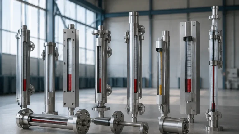
Gauges Labeled
Gauges Labeled
In industrial process control, the term "gauges labeled" refers to more than just a sticker on a piece of equipment. It encompasses the critical identification, scale calibration, and safety marking systems required for the safe and accurate operation of level measurement instruments. For engineers and plant operators, ensuring that magnetic and local level gauges are correctly labeled is a fundamental aspect of facility safety, regulatory compliance, and operational efficiency.
Local level indication remains a cornerstone of industrial automation, providing a mechanical, power-independent backup to electronic transmitters. Whether in water treatment, chemical processing, or oil and gas applications, the clarity of the information displayed on the gauge face is paramount. This guide explores the engineering principles behind Magnetic & Local Level Gauges, the technical requirements for labeling, and the practical considerations for selecting and maintaining these instruments.
Measurement Principles of Magnetic Level Gauges
To understand why labeling is so critical, one must first understand how these instruments function. A magnetic level gauge operates on the principles of buoyancy and magnetic coupling. Unlike traditional glass sight gauges, which expose the process fluid to a fragile glass tube, magnetic gauges utilize a robust metal bypass chamber.
The Bypass Chamber and Float
The instrument consists of a vertical chamber connected to the process vessel via two nozzles (top and bottom). As the liquid level in the vessel rises or falls, the level inside the bypass chamber matches it. Inside this chamber is a float specifically engineered for the density (specific gravity) of the process fluid. This float contains a high-strength permanent magnet assembly.
Magnetic Coupling and Indication
Mounted to the outside of the chamber is the indicator rail. This rail is hermetically sealed and contains a series of bi-color magnetic flaps or a magnetic follower. As the float moves with the liquid level, its internal magnetic field couples with the external indicator. This causes the flaps to rotate (typically from white to red or yellow) or the follower to move, providing a clear, high-visibility representation of the liquid level without any physical contact between the process fluid and the indicator.
The Role of Gauges Labeled for Safety and Identification
When we discuss gauges labeled in a B2B or engineering context, we are looking at three distinct layers of information: identification, measurement scales, and safety warnings.
1. Identification (Tagging)
Every instrument in a plant must have a unique identifier, often referred to as a "Tag Number." These are typically stainless steel tags wired to the gauge or engraved directly onto the chamber. This label allows maintenance teams to cross-reference the gauge with P&IDs (Piping and Instrumentation Diagrams) and digital asset management systems. A gauge labeled correctly ensures that the right maintenance procedure is applied to the right instrument.
2. Measurement Scales
The scale is the most visible label on the gauge. Depending on the application, scales may be labeled in:
* Linear Height: Millimeters (mm) or inches (in) to show the actual physical height of the liquid.
* Percentage: 0-100% of the visible range.
* Volumetric Units: Liters, cubic meters, or gallons, which require a strapping table calculation if the tank is non-cylindrical.
3. Process and Safety Information
Critical gauges must be labeled with their design limits. This includes the maximum allowable working pressure (MAWP) and the design temperature range. In high-temperature applications, gauges labeled with "Caution: Hot Surface" help prevent workplace injuries. Furthermore, labeling the specific gravity for which the float was designed is essential; if the process fluid changes, the float may no longer track accurately, leading to false readings.
Technical Selection Criteria
Selecting the right gauge requires a thorough understanding of the process environment. Welk provides various configurations to meet these needs. The following table outlines key selection parameters for magnetic and local level gauges.
Selection Table: Magnetic Level Gauge Specifications
| Feature | Standard Configuration | High-Pressure Configuration | Cryogenic/Low Temp |
| :— | :— | :— | :— |
| Chamber Material | SS304 / SS316L | SS316Ti / Hastelloy | SS316L with Frost Shield |
| Max Pressure | 4.0 MPa (40 bar) | Up to 25 MPa (250 bar) | 2.5 MPa (25 bar) |
| Temperature Range | -20°C to 150°C | Up to 450°C | Down to -196°C |
| Connection Size | DN20 / DN25 (1") | DN25 / DN50 (2") | DN25 (1") |
| Accuracy | ±10 mm | ±10 mm | ±10 mm |
| Indicator Type | Bi-color Flaps | Bi-color Flaps | Magnetic Follower |
Installation and Calibration Considerations
For a gauge to provide accurate data, the physical installation must be precise. Because magnetic level gauges rely on a floating element, vertical alignment is the most critical factor.
Verticality
The chamber must be installed within 3° of true vertical. If the gauge is tilted, the float may experience friction against the chamber walls, leading to "sticking" or erratic movement. This is particularly important in high-viscosity fluids where the clearance between the float and the chamber is minimal.
Isolation Valves
It is recommended to install isolation valves (usually ball or gate valves) between the process vessel and the gauge chamber. This allows for the gauge to be cleaned or the float to be replaced without depressurizing the entire tank. Gauges labeled with the valve positions (Open/Closed) further enhance operational safety.
Vent and Drain Connections
Standard gauges should include a vent plug at the top and a drain valve at the bottom. These are used to flush the chamber of sediment or debris that could interfere with float movement. In chemical applications, these drains must be piped to a safe recovery area.

Limitations and Environmental Factors
While magnetic level gauges are highly versatile, they have specific limitations that engineers must consider during the design phase.
* Magnetic Interference: Because the system relies on magnetic coupling, the gauge should be kept away from large motors, high-voltage power lines, or other strong electromagnetic fields that could disrupt the flap rotation.
* Ferrous Particles: If the process fluid contains iron filings or magnetic scale, these particles will adhere to the internal float magnet. Over time, this build-up will cause the float to become heavy or stuck. In such cases, a magnetic filter or trap should be installed upstream of the gauge.
* Coating and Buildup: Highly viscous fluids or fluids that crystallize can coat the float and the interior of the chamber. Regular flushing is required to maintain accuracy in these environments.
Integration with Industrial Automation
Modern magnetic level gauges are often used as the foundation for a multi-layered measurement solution. While the visual scale provides local indication, many units are fitted with:
1. Reed Switches: These are clamped to the outside of the chamber and are triggered by the float's magnet to provide high or low-level alarms.
2. Magnetostrictive Transmitters: These provide a continuous 4-20mA or HART signal to a PLC or DCS, allowing for remote monitoring. Because the transmitter is mounted externally, it can be serviced without breaching the process seal.
When these accessories are used, the gauges labeled with electrical safety ratings (such as ATEX or IECEx for hazardous areas) become critical for insurance and safety audits.
Maintenance and Troubleshooting FAQ
Q: Why are the indicator flaps not changing color even though the level is rising?
A: This is usually caused by a "stuck" float. This can happen if the chamber is not vertical, if there is significant debris inside, or if the process fluid density has decreased below the float's design limit. Check the gauges labeled specific gravity against the current fluid properties.
Q: Can I use a magnetic level gauge for interface measurement (e.g., oil over water)?
A: Yes. However, the float must be weighted specifically to sink through the upper (lighter) liquid and float on the lower (heavier) liquid. The gauge should be clearly labeled "Interface Service" to prevent confusion with total level measurement.
Q: How often should the scale be recalibrated?
A: Since the measurement is based on physical buoyancy, the "calibration" does not drift like electronic sensors. However, the scale should be inspected annually to ensure it remains securely attached and that the labels are legible and have not faded due to UV exposure.
Q: What is the benefit of a "gauges labeled" system in a high-pressure environment?
A: In high-pressure systems, visual confirmation is the final line of defense. Clear labeling of pressure ratings ensures that operators do not accidentally introduce pressures exceeding the design limits of the bypass chamber, which could lead to catastrophic failure.
Conclusion
In the world of industrial instrumentation, the small details often carry the most weight. A magnetic level gauge is a robust and reliable tool, but its value is significantly diminished if it is not correctly identified and calibrated. By adhering to strict standards for gauges labeled with tag numbers, scales, and safety data, facilities can ensure that their personnel have the information they need to operate safely.
For engineers seeking reliable, high-visibility solutions, Welk offers a range of Magnetic & Local Level Gauges designed to withstand the rigors of modern industrial environments. Whether you are dealing with corrosive chemicals or high-pressure steam, ensuring your instruments are correctly selected, installed, and labeled is the first step toward operational excellence.