Volume Level Gauge
Volume Level Gauge
In industrial process control, the distinction between measuring the height of a liquid and determining its actual quantity is critical. While a standard level sensor identifies the position of the liquid surface, a volume level gauge provides the necessary data to calculate the total inventory within a vessel. This distinction is particularly vital in custody transfer, chemical dosing, and inventory management where the geometry of the tank dictates that a linear change in height does not always correspond to a linear change in volume.
For engineers and plant managers, selecting the correct instrumentation requires an understanding of how level data is converted into volume metrics. This guide explores the principles, selection criteria, and practical applications of Magnetic & Local Level Gauges and other technologies used to monitor volume in industrial environments.
The Relationship Between Level and Volume
Before recommending specific hardware, it is essential to define the mathematical relationship between the measured level ($h$) and the stored volume ($V$). In a perfectly vertical cylinder with a flat bottom, the relationship is linear: $V = A \times h$, where $A$ is the cross-sectional area. However, industrial tanks are rarely this simple.
Non-Linear Tank Geometries
In many applications, such as horizontal cylindrical tanks or vessels with conical or hemispherical bottoms, the volume per unit of height changes as the level rises. For example, in a horizontal tank, a 100 mm increase in level near the bottom represents significantly less volume than a 100 mm increase near the center of the tank.
To function as an effective volume level gauge, the measurement system must account for these geometric variables. This is typically achieved through:
1. Strapping Tables: A manual or digital look-up table that correlates specific height increments to known volumes.
2. Geometric Formulas: Integrated algorithms within a transmitter that calculate volume based on entered tank dimensions.
3. Custom Scales: For local indicators like magnetic level gauges, the physical scale can be graduated in units of volume (liters, cubic meters) rather than just height (millimeters).
Principles of Magnetic and Local Level Gauges
Magnetic level gauges are among the most reliable instruments for local volume monitoring, especially in high-pressure or hazardous environments. They operate on the principle of magnetic coupling and buoyancy.
How They Work
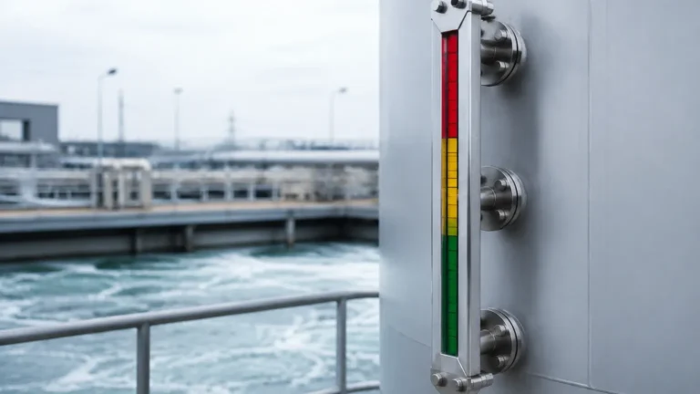
A magnetic level gauge consists of a bypass chamber (a standpipe) mounted to the side of the tank. Inside this chamber is a float containing a high-intensity magnet. As the liquid level in the tank rises and falls, the float moves accordingly within the chamber. Outside the chamber, a visual indicator—typically a series of bi-color flaps or a follower—is magnetically coupled to the float. As the float moves, the magnets flip the flaps or move the follower, providing a clear, high-visibility representation of the liquid level.
Because the indicator is completely isolated from the process fluid, these gauges are ideal for toxic, corrosive, or flammable liquids. To serve as a volume level gauge, the external scale is calibrated based on the tank's strapping table, allowing operators to read the volume directly from the gauge face.
Technical Selection Criteria
When specifying a volume level gauge, several technical factors must be evaluated to ensure accuracy and safety. The following table summarizes the primary considerations for different gauge types.
| Feature | Magnetic Level Gauges | Ultrasonic Level Sensors | Hydrostatic Transmitters |
| :— | :— | :— | :— |
| Measurement Type | Contact (Float-based) | Non-contact | Contact (Pressure-based) |
| Accuracy | ±5 mm to ±10 mm | ±0.25% of range | ±0.1% to ±0.5% of span |
| Max Temperature | Up to 450°C | Generally < 80°C | Up to 120°C (standard) |
| Max Pressure | Up to 200 bar | Atmospheric | Dependent on sensor rating |
| Visibility | Excellent local visual | Digital display only | Digital display only |
| Volume Conversion| Graduated scale/Transmitter| Built-in software | External PLC/Controller |
Fluid Density and Buoyancy
For magnetic gauges, the density of the fluid is a critical factor. The float must be engineered to be buoyant enough to sit at the surface of the liquid but heavy enough to remain stable. If the fluid density changes significantly due to temperature fluctuations, the float's immersion depth will change, leading to a small error in the volume reading. Welk engineers typically require the minimum specific gravity of the fluid to design the float correctly.
Chemical Compatibility
The materials of construction for the chamber and float must resist the process media. Common materials include:
* 316L Stainless Steel: Standard for water, oils, and mild chemicals.
* Hastelloy or Titanium: For highly corrosive acids or seawater.
* PVC/CPVC/PVDF: For low-pressure chemical storage where metals are unsuitable.
Installation Considerations for Volume Accuracy
To ensure a volume level gauge provides reliable data, installation must follow strict engineering guidelines. Even the most accurate sensor will provide false volume readings if installed incorrectly.
1. Vertical Alignment: Local gauges must be installed perfectly vertical. Any tilt can cause friction between the float and the chamber wall, leading to "sticking" and inaccurate readings.
2. Nozzle Placement: The bypass nozzles should be placed away from turbulent areas, such as near agitators or high-velocity inlet pipes. Turbulence can cause the float to bounce, creating "noise" in the measurement.
3. Venting and Draining: The bypass chamber must be properly vented at the top and have a drain valve at the bottom. This allows for maintenance and ensures the liquid level in the chamber accurately reflects the level in the tank by preventing air pockets.
4. Isolation Valves: Installing isolation valves between the tank and the gauge allows for the instrument to be serviced without draining the entire vessel.

Limitations and Practical Constraints
While magnetic and local gauges are robust, they are not universal solutions.
* Coating and Buildup: If the process fluid is highly viscous or prone to crystallization, the float may become stuck or the chamber may clog. In these instances, internal coatings like PTFE or high-frequency cleaning intervals are required.
* Magnetic Interference: Because the gauge relies on magnetic coupling, it should not be installed near large motors or high-voltage power lines that could create electromagnetic interference.
* Extreme Lengths: For very tall tanks (exceeding 6 meters), the weight of the bypass chamber becomes a structural concern. In these cases, the gauge may need to be manufactured in sections or supported by external brackets.
* Interface Measurement: Measuring the volume of two different liquids in the same tank (e.g., oil and water) requires a float specifically weighted to sink through the upper layer and float on the lower layer. This is a specialized application of the volume level gauge principle.
Calibration and Maintenance
Regular maintenance ensures that a volume level gauge remains an authoritative source of data. For local gauges, maintenance is relatively simple but essential.
* Visual Inspection: Periodically check the indicator flags for damage or fading. Ensure the glass or polycarbonate cover is clean.
* Flushing the Chamber: Periodically open the drain valve to flush out any sediment that may have settled at the bottom of the chamber. This prevents the float from becoming obstructed.
* Transmitter Calibration: If the gauge is equipped with a reed chain or magnetostrictive transmitter for remote volume monitoring, the 4-20mA or HART signal should be verified against the physical scale at least once a year.
Frequently Asked Questions (FAQ)
Q: Can a volume level gauge measure solids or powders?
A: Most local gauges, particularly magnetic types, are designed for liquids. For solids or powders, non-contact methods like radar or ultrasonic sensors are preferred, as floats cannot move through bulk solids.
Q: How do I handle volume measurement in a tank with an internal agitator?
A: A bypass magnetic gauge is ideal for this scenario. Because the measurement happens in an external chamber, the turbulence and foam created by the agitator do not affect the stability of the float or the accuracy of the reading.
Q: What is the maximum pressure a magnetic volume gauge can handle?
A: High-pressure versions can be engineered to handle up to 200 bar (approx. 2900 PSI) or more, depending on the wall thickness of the chamber and the design of the float.
Q: Is it possible to get a digital output for volume from a local gauge?
A: Yes. By adding a magnetostrictive transmitter to the exterior of the magnetic gauge chamber, the position of the float can be converted into a digital signal (HART, Modbus, or Profibus) and sent to a PLC, which then calculates the volume based on a pre-programmed strapping table.
Conclusion
Selecting a volume level gauge is a process that begins with understanding the physical characteristics of the vessel and the chemical nature of the fluid. Whether using a simple graduated scale on a magnetic gauge or an integrated digital system, the goal remains the same: providing an accurate, repeatable measure of inventory. By adhering to proper selection criteria and installation practices, industrial facilities can ensure safety, reduce waste, and optimize their process efficiency.