Level Gauge P&id
Level Gauge P&id
In the realm of process engineering and industrial automation, the Piping and Instrumentation Diagram (P&ID) serves as the definitive blueprint for any facility. Within these complex schematics, the representation of level measurement instruments is critical for ensuring operational safety, process efficiency, and accurate inventory management. A level gauge p&id entry is more than just a symbol; it represents a physical interface between the process fluid and the operator, providing a direct, local reading of the vessel's contents.
For engineers and project managers working with brands like Welk, understanding how to correctly specify and interpret Magnetic & Local Level Gauges on a P&ID is essential for successful system integration. This guide explores the technical principles, symbolic representations, and selection criteria necessary for effective level gauge implementation.
Measurement Principles of Magnetic & Local Level Gauges
Before detailing how these instruments appear on a P&ID, it is vital to understand the physics that govern their operation. Local level gauges are generally categorized into two main types: direct-view glass gauges and magnetic level gauges.
Direct-View Glass Gauges (Reflex and Transparent)
Direct-view gauges operate on the principle of communicating vessels. A chamber is connected to the side of a tank, and the liquid level in the chamber rises and falls in tandem with the level in the tank.
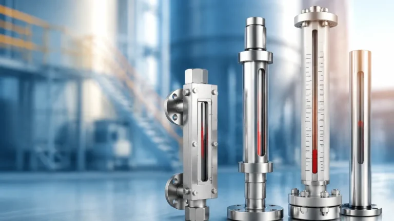
* Reflex Gauges: These utilize the law of light refraction. The glass has prismatic grooves. In the gas/vapor space, light is reflected, appearing bright white. In the liquid space, light is absorbed, appearing dark. This high-contrast transition makes it easy to read clear liquids.
* Transparent Gauges: These use two clear glasses on opposite sides of the chamber. This allows light to pass through the fluid, which is necessary for observing the color, interface, or clarity of the medium. They are often equipped with mica shields to protect the glass from corrosive media like steam or caustic soda.
Magnetic Level Gauges (MLGs)
Magnetic level gauges utilize the principle of buoyancy and magnetic coupling. A float containing a permanent magnet assembly is placed inside a non-magnetic bypass chamber. As the liquid level changes, the float moves accordingly. Outside the chamber, a column of interlocking magnetic flaps (usually colored red and white) or a magnetic follower reacts to the float's magnetic field.
As the float passes, the flaps flip 180 degrees, changing color to indicate the current level. Because the liquid is entirely contained within the pressure-sealed chamber, MLGs eliminate the risk of glass breakage and leaks, making them the preferred choice for high-pressure or hazardous chemical applications.
Interpreting the Level Gauge P&ID Symbolism
On a P&ID, every instrument is assigned a tag and a symbol that defines its function and location. The standard notation for a level gauge is typically "LG" followed by a unique loop number (e.g., LG-101).
Common P&ID Symbols for Level Gauges
1. The Circle (Bubble): A simple circle containing the letters "LG" indicates a local instrument mounted directly on the process equipment. If there is no line through the circle, it means the gauge is only accessible locally at the equipment site.
2. The Connecting Lines: In a level gauge p&id representation, the lines connecting the LG bubble to the vessel (the "lead lines") represent the process piping connections. These should ideally show the isolation valves, which are crucial for maintenance.
3. LIG vs. LG: Sometimes you will see "LIG" (Level Indicating Gauge). While "LG" is the standard, "LIG" emphasizes that the device provides a visual indication. If the magnetic gauge is also equipped with a transmitter for remote monitoring, the P&ID will show a separate circle for "LT" (Level Transmitter) or "LIT" (Level Indicating Transmitter) connected to the same bypass chamber.
Selection Criteria for P&ID Specification
Specifying the correct gauge during the P&ID development phase requires a thorough evaluation of the process conditions. Engineers must determine if a standard glass gauge is sufficient or if the safety profile of a magnetic gauge is required.
Process Temperature and Pressure
Standard glass gauges have physical limits regarding thermal shock and high-pressure integrity. For pressures exceeding 40 bar (approx. 580 PSI) or temperatures above 250°C (482°F), magnetic level gauges are often mandated. The bypass chamber of an MLG can be engineered to withstand pressures up to 250 bar and temperatures exceeding 400°C.
Fluid Characteristics
* Corrosivity: For highly corrosive acids, a magnetic gauge with a PTFE or PFA lining is often safer than glass, which can etch over time.
* Viscosity and Coating: If a fluid is highly viscous or prone to coating (like heavy crude oil), a reflex glass gauge may become unreadable. Magnetic gauges are less sensitive to coating because the magnetic field can penetrate thin layers of buildup on the chamber wall.
* Specific Gravity: Magnetic floats must be weighted specifically to the density of the process fluid. If the specific gravity (SG) is too low (e.g., below 0.4), the float may become too large for standard chambers.
Installation Requirements and Piping Configurations
A well-designed level gauge p&id must account for the physical installation requirements to ensure the gauge operates accurately and can be maintained safely.
Nozzle Placement and Orientation
Level gauges are typically mounted on the side of a vessel using two nozzles (top and bottom). The distance between these nozzles is known as the "Center-to-Center" (C-C) distance. It is standard practice to ensure the visible range of the gauge covers the entire operating range of the vessel, including the high and low alarm setpoints.
Isolation, Vent, and Drain
To comply with safety standards, every level gauge installation should include:
* Isolation Valves: Usually ball or gate valves located between the vessel nozzles and the gauge. These allow the gauge to be removed or repaired without depressurizing the entire vessel.
* Vent Valve: Located at the top of the gauge chamber to release trapped gas or air during commissioning or maintenance.
* Drain Valve: Located at the bottom to empty the liquid from the chamber before removal.
In a level gauge p&id, these valves should be clearly drawn to ensure the piping team includes them in the final construction.

Comparison of Local Level Gauging Technologies
The following table provides a comparison to assist in the selection process during the engineering phase.
| Feature | Reflex Glass Gauge | Transparent Glass Gauge | Magnetic Level Gauge |
| :— | :— | :— | :— |
| Primary Application | Clean, clear liquids | Interface, colored liquids | Hazardous, high-pressure |
| Visibility | High contrast (Black/White) | Requires backlight | Excellent (Colored flaps) |
| Max Pressure (Metric) | Up to 40 bar | Up to 120 bar | Up to 250+ bar |
| Max Temp (Metric) | Up to 300°C | Up to 400°C | Up to 450°C |
| Risk of Leakage | Moderate (Glass/Gasket) | Moderate (Glass/Gasket) | Very Low (Sealed Chamber) |
| Maintenance | High (Cleaning glass) | High (Cleaning glass) | Low (Float check) |
| Remote Signal | No | No | Yes (With optional LT) |
Limitations and Operational Risks
While Magnetic & Local Level Gauges are robust, they are not without limitations. Engineers must be aware of these risks when finalizing the level gauge p&id.
1. Magnetic Interference: Magnetic gauges should not be installed near large motors or high-voltage power lines that could create electromagnetic fields, as these can interfere with the float's magnetic coupling to the indicator.
2. Particulate Accumulation: If the process fluid contains magnetic particles (such as iron filings or magnetite), they can accumulate on the float's magnet, increasing its weight and causing it to sink or stick. In such cases, a magnetic trap should be installed in the piping.
3. Flashing and Boiling: If the liquid in the chamber flashes into vapor due to a pressure drop or temperature change, the resulting turbulence can cause the float to bounce violently, leading to inaccurate readings or damage to the float.
4. Glass Fragility: For glass gauges, the primary risk is mechanical impact or thermal shock. Protective shields and proper heat tracing can mitigate these risks, but they remain a point of vulnerability compared to all-metal magnetic gauges.
Frequently Asked Questions
1. Why is a magnetic level gauge preferred over a sight glass in chemical plants?
Magnetic level gauges are preferred because they provide a "total containment" solution. There is no glass to break, and the fluid is contained within a pressure-rated metal chamber. This significantly reduces the risk of toxic or flammable leaks in hazardous environments.
2. How do I represent a level gauge with a transmitter on a P&ID?
On a level gauge p&id, you would typically show the bypass chamber connected to the vessel. Attached to this chamber, you would draw two bubbles: one for the LG (the local indicator) and one for the LT (the transmitter). A dashed line usually connects the LT to the control system (DCS/PLC).
3. What is the standard units of measurement for level gauges?
In international projects, metric units are standard. Visibility and C-C distances are measured in millimeters (mm), and pressure is measured in bar or kPa. However, imperial units (inches and PSI) are still widely used in the North American market.
4. Can magnetic level gauges measure the interface between two liquids?
Yes, by adjusting the weight of the float to a density between the specific gravities of the two liquids, the float will sink through the top layer and float on the bottom layer, effectively indicating the interface level.
Conclusion
The accurate representation of a level gauge p&id is a fundamental step in industrial plant design. Whether opting for the simplicity of a reflex glass gauge or the advanced safety of a magnetic level gauge, engineers must ensure that the chosen technology aligns with the process temperature, pressure, and fluid characteristics. By following established P&ID conventions and considering installation requirements like isolation and venting, facilities can ensure long-term reliability and operator safety. For those seeking high-performance hardware, Welk offers a comprehensive range of solutions designed to meet the rigorous demands of modern industrial automation.