V Gauges
V Gauges
In the landscape of industrial process control, the term "V gauges"—frequently used as shorthand for visual level gauges or local level indicators—represents a critical category of instrumentation. These devices provide a direct, mechanical, and highly reliable method for monitoring liquid levels within tanks, pressure vessels, and boilers. Unlike electronic sensors that may require complex calibration or external power, V gauges offer an immediate, "at-a-glance" verification of the process state, serving as the primary local reference for plant operators and maintenance engineers.
Welk, a professional manufacturer of level measurement instruments, emphasizes the importance of integrating robust local indicators into any industrial automation system. Whether used in water treatment, chemical processing, or oil and gas applications, these gauges bridge the gap between automated control systems and manual safety verification.
Understanding the Principles of Visual Level Measurement
The fundamental operation of most V gauges relies on the principle of communicating vessels. This physical law states that in a set of connected containers, a liquid will reach the same level in each container, regardless of their shape or volume, provided the pressure remains constant across the surface of the liquid.
The Communicating Vessels Principle
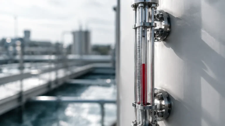
In a standard bypass or side-mounted configuration, the gauge is connected to the side of a vessel via two nozzles (top and bottom). As the liquid level rises or falls within the main tank, the level within the gauge chamber moves in tandem. This allows the operator to observe the internal liquid level through a transparent medium or via a magnetic coupling mechanism.
Magnetic Coupling vs. Direct Sight
Modern industrial applications often distinguish between two primary methods of visual indication:
1. Direct Sight (Glass Gauges): These use high-strength borosilicate glass to allow the operator to see the actual liquid. These are categorized into reflex and transparent types.
2. Magnetic Coupling: These utilize a float containing a permanent magnet. As the float moves with the liquid level, it interacts with an external indicator (such as a series of bicolored flaps or a follower). This method is preferred for hazardous or high-pressure fluids because it eliminates the risk of glass breakage and leakage.
Types of V Gauges in Industrial Applications
When selecting Magnetic & Local Level Gauges, it is essential to understand the specific mechanical configurations available and how they interact with different process media.
Magnetic Level Gauges
Magnetic level gauges are the modern standard for safety-critical environments. The chamber is typically constructed from non-magnetic stainless steel or plastic. Inside, a custom-weighted float is engineered to match the specific gravity of the process liquid. The external indicator strip is isolated from the process fluid, meaning there is no risk of leaks even if the indicator is damaged. This design is particularly effective for toxic, flammable, or high-pressure substances.
Reflex Level Gauges
Reflex gauges utilize a single piece of glass with prismatic grooves molded into the side facing the liquid. These grooves use the principle of light refraction to create a sharp contrast between the liquid and the vapor space. The liquid-filled area appears dark (usually black), while the vapor space appears bright (silvery). This makes them excellent for clean, colorless liquids where a standard transparent gauge might be difficult to read.
Transparent Level Gauges
Transparent gauges feature two pieces of flat glass on opposite sides of the chamber. This allows light to pass through the gauge, making it possible to observe the color, clarity, and interface of the liquid. These are the preferred choice for measuring the interface between two immiscible liquids (e.g., oil and water) or for processes where the liquid's color is a key quality indicator.
Selection Criteria for V Gauges
Choosing the correct V gauges requires a detailed analysis of the process environment. A mismatch between the gauge material and the process fluid can lead to catastrophic failure or inaccurate readings.
Key Evaluation Factors
* Specific Gravity: For magnetic gauges, the float must be precisely calibrated. If the specific gravity of the fluid changes due to temperature fluctuations, the float may sink or ride too high.
* Pressure and Temperature: Glass-based gauges have strict limits based on the thickness and type of glass. Magnetic gauges can handle much higher pressures, often exceeding 200 bar (2900 psi).
* Fluid Compatibility: The wetted parts (chamber, float, and gaskets) must be resistant to corrosion. Common materials include 316L Stainless Steel, Hastelloy, PVC, and PTFE lining.
* Visibility Requirements: Consider the distance from which the gauge must be read. Magnetic indicators with high-contrast flaps are visible from much further distances than traditional glass gauges.
Practical Selection Table
| Feature | Magnetic Level Gauges | Reflex Glass Gauges | Transparent Glass Gauges |
| :— | :— | :— | :— |
| Max Pressure | Up to 250 bar (3625 psi) | Up to 100 bar (1450 psi) | Up to 100 bar (1450 psi) |
| Max Temperature | Up to 450°C (842°F) | Up to 400°C (752°F) | Up to 400°C (752°F) |
| Visibility | Excellent (Long distance) | Good (High contrast) | Moderate (Requires backlight) |
| Hazardous Fluids | Highly Recommended | Limited | Limited |
| Interface Detection | Possible with dual floats | Not Recommended | Excellent |
| Maintenance | Low | Moderate (Glass cleaning) | Moderate (Glass cleaning) |

Installation and Maintenance Considerations
Proper installation is paramount to the accuracy and safety of v gauges. Since these are mechanical devices, physical alignment and environmental factors play a significant role in their performance.
Installation Checklist
1. Vertical Alignment: The gauge chamber must be installed perfectly vertical. Any tilt can cause the float in a magnetic gauge to bind against the chamber walls, leading to stuck readings.
2. Isolation Valves: Always install high-quality isolation valves between the vessel and the gauge. This allows for maintenance or glass replacement without shutting down the entire process.
3. Venting and Draining: Every gauge should be equipped with a vent valve at the top and a drain valve at the bottom. This is necessary for clearing debris, sampling the fluid, and safely depressurizing the unit before maintenance.
4. Support Brackets: For long gauges (typically those exceeding 3 meters or 10 feet), intermediate support brackets are required to prevent vibration and mechanical stress on the process connections.
Maintenance Best Practices
* Regular Flushing: Periodically drain the gauge to remove sediment or scale buildup that could interfere with the float or obscure the glass.
* Gasket Inspection: For glass gauges, gaskets should be replaced whenever the gauge is disassembled. Reusing gaskets often leads to leaks under thermal expansion.
* Magnetic Verification: For magnetic gauges, a simple test with an external magnet can ensure the indicator flaps are moving freely and have not become demagnetized over time.
Limitations and Safety Risks
While V gauges are highly reliable, they are not without limitations. Engineers must be aware of these constraints during the design phase.
* Coating and Fouling: Liquids that are highly viscous or prone to crystallization can coat the internal walls of the chamber or the surface of the glass. In magnetic gauges, this can cause the float to stick. In glass gauges, it renders the device unreadable.
* Glass Fragility: In high-vibration environments or areas prone to thermal shock, glass gauges pose a safety risk. A sudden splash of cold water on a hot gauge glass can cause it to shatter, releasing process fluid.
* Extreme Specific Gravity: If a liquid has an extremely low specific gravity (e.g., certain liquefied gases), designing a float that is light enough to float yet strong enough to withstand the pressure can be a significant engineering challenge.
Frequently Asked Questions (FAQs)
Q: Can V gauges be used for steam boiler applications?
A: Yes, but they must be specifically rated for steam service. Transparent gauges with mica shields are typically used to protect the glass from the corrosive effects of high-temperature steam and boiler water chemicals.
Q: How do I choose between a reflex and a magnetic level gauge?
A: Choose a reflex gauge for simple, non-hazardous, clean liquids where cost is a primary factor. Choose a magnetic level gauge for high-pressure, toxic, or flammable fluids, or when you need to transmit the level signal electronically (as many magnetic gauges can be fitted with reed switches or transmitters).
Q: What is the maximum length for a single V gauge?
A: While chambers can be manufactured in very long sections, glass gauges are usually limited to about 3 meters (10 feet) due to the weight and fragility of the glass. Magnetic level gauges can be much longer, often up to 6 meters (20 feet) or more, though they may require sectional shipping and field assembly.
Q: Do magnetic V gauges require power?
A: The visual indication part of a magnetic level gauge is entirely mechanical and requires no power. However, if you add a 4-20mA transmitter or limit switches to the chamber for remote monitoring, those components will require a power supply.
Q: How often should the gauge glass be replaced?
A: There is no fixed schedule, but glass should be inspected during every plant turnaround. If any clouding, scratching, or thinning (erosion) is observed, the glass and gaskets should be replaced immediately to prevent failure.
By understanding the mechanical principles and selection criteria for V gauges, industrial facilities can ensure accurate local monitoring that enhances both operational efficiency and site safety. Welk continues to provide advanced Magnetic & Local Level Gauges tailored to the rigorous demands of global industrial automation.