W Gauges
W Gauges
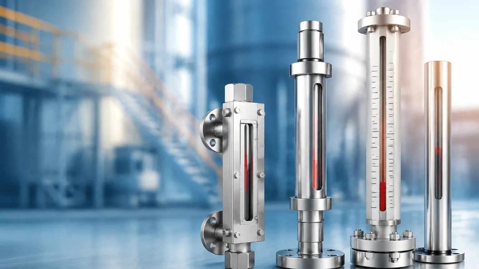
In industrial process control, the ability to monitor liquid levels locally and accurately is a fundamental requirement for safety and operational efficiency. W gauges, often a shorthand designation for various types of water or liquid level gauges including reflex, transparent, and magnetic variants, serve as the primary visual interface between the process fluid and the operator. These instruments provide a real-time, mechanical verification of the level inside a tank or pressure vessel, functioning independently of electronic control systems.
Selecting the appropriate local level indicator requires a deep understanding of the physical properties of the media, the mechanical constraints of the vessel, and the environmental conditions of the plant. As a professional manufacturer, Welk provides a range of Magnetic & Local Level Gauges designed to meet the rigorous demands of water treatment, chemical processing, and oil and gas industries.
Measurement Principles of Local Level Gauges
Before selecting a specific gauge, it is essential to understand the physics governing their operation. Local level gauges generally fall into two categories: those based on optical refraction and those based on magnetic buoyancy.
The Buoyancy and Magnetic Coupling Principle
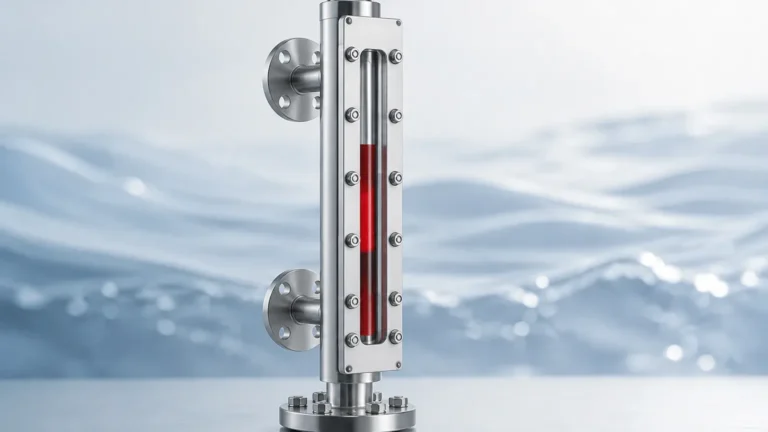
Magnetic level gauges operate on the principle of communicating vessels; the liquid level in the gauge chamber corresponds exactly to the level in the main tank. Inside the chamber is a float specifically engineered to match the density of the process fluid. This float contains a high-intensity permanent magnet.
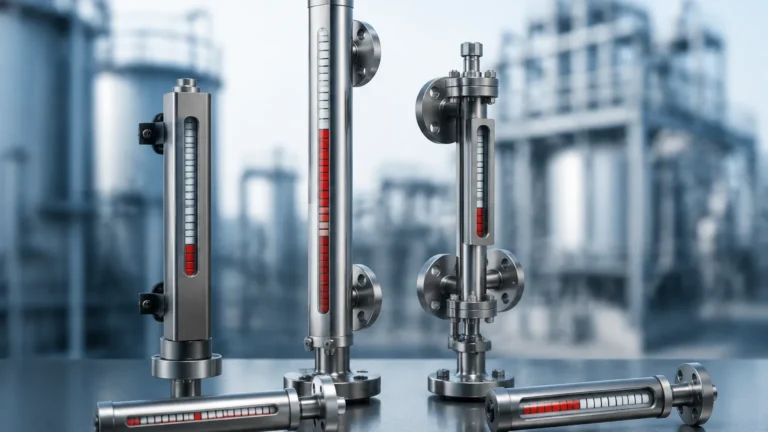
As the float rises or falls with the liquid level, its internal magnetic field acts through the wall of the non-magnetic chamber (usually stainless steel) to affect an external indicator. This indicator typically consists of a series of bi-color magnetic flaps or rollers. As the float passes, the flaps flip 180 degrees, changing color (e.g., from white to red) to provide a clear, high-contrast visual representation of the liquid level. This method eliminates the need for direct contact between the operator and the process fluid, significantly increasing safety in high-pressure or toxic applications.
Optical Refraction (Reflex and Transparent)
Traditional glass-style W gauges utilize the optical properties of light.
* Reflex Gauges: These use a prism-shaped glass. When light enters the gauge, it is reflected back in the gas space (appearing silvery/white) and absorbed in the liquid space (appearing dark/black). This creates a sharp line of demarcation at the liquid level.
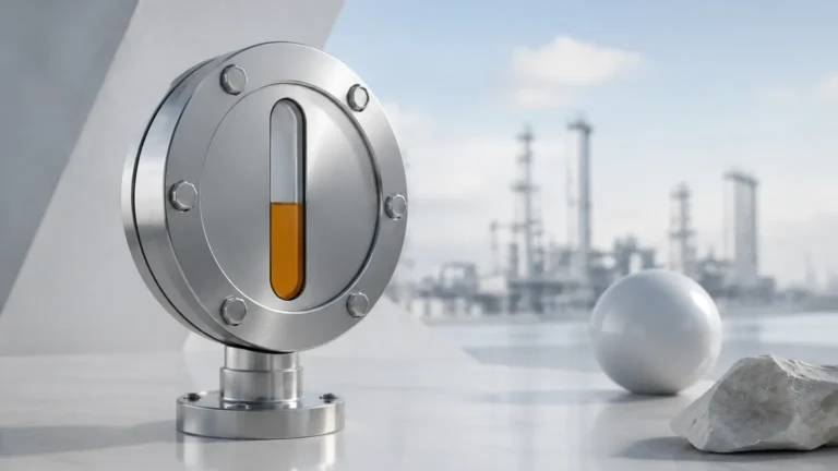
* Transparent Gauges: These feature two pieces of flat glass on opposite sides of the chamber. Light travels through the gauge, allowing the operator to see the actual color, clarity, or interface of the liquid. This is essential for applications involving interface measurement between two liquids or where the color of the fluid must be monitored.
Technical Comparison of W Gauge Types
Choosing the right technology depends on the specific needs of the application, such as visibility requirements, chemical compatibility, and pressure ratings.
| Feature | Magnetic Level Gauges | Reflex Glass Gauges | Transparent Glass Gauges |
| :— | :— | :— | :— |
| Visibility | Excellent (up to 30m away) | Good (High contrast) | Moderate (Requires backlight) |
| Max Pressure | Up to 320 bar (32 MPa) | Up to 250 bar (25 MPa) | Up to 250 bar (25 MPa) |
| Max Temperature | Up to 450°C | Up to 400°C | Up to 400°C |
| Safety | High (No glass to break) | Moderate (Glass risk) | Moderate (Glass risk) |
| Media Compatibility | Wide (Corrosive/Toxic) | Limited by glass/gaskets | Limited by glass/gaskets |
| Maintenance | Low | Moderate (Gasket leaks) | Moderate (Cleaning glass) |
Key Selection Criteria for Industrial Applications
When specifying W gauges for a project, several technical parameters must be confirmed to ensure the longevity and accuracy of the instrument.
1. Fluid Density (Specific Gravity)
For magnetic level gauges, the specific gravity (SG) of the fluid is the most critical factor. The float must be buoyant enough to sit at the surface of the liquid but heavy enough to remain stable. Welk engineers floats based on the exact SG provided by the client, often accommodating fluids with densities as low as 0.45 g/cm³.
2. Operating Pressure and Temperature
Standard glass gauges are limited by the physical strength of the borosilicate glass and the integrity of the gaskets. In high-temperature steam applications, glass can suffer from "thinning" due to the corrosive nature of pure water at high temperatures. Magnetic gauges are often preferred for high-pressure steam (above 35 bar) because they utilize a solid metal chamber rather than a glass window.
3. Material Compatibility
The wetted parts of the gauge—the chamber, float, and process connections—must be resistant to the process media. Common materials include:
* 304/316L Stainless Steel: Standard for water and general chemicals.
* PTFE/PFA Lining: Used for highly aggressive acids or bases.
* Titanium or Hastelloy: For specialized high-corrosion environments in the chemical industry.
Installation and Configuration Guidelines
Proper installation is paramount to the accuracy and safety of W gauges. Failure to follow standard engineering practices can lead to mechanical stress on the gauge or inaccurate readings.
Orientation and Mounting
Gauges are typically side-mounted to the vessel using flanges or NPT/BSP threaded connections. It is vital that the gauge is perfectly vertical. A tilt of even a few degrees can cause the internal float in a magnetic gauge to rub against the chamber walls, leading to friction that prevents the float from moving smoothly.
Venting and Draining
Every local level gauge should be equipped with a vent valve at the top and a drain valve at the bottom. This allows for:
* Commissioning: Air trapped in the gauge chamber can prevent the liquid from entering; venting ensures the gauge fills correctly.
* Maintenance: The gauge must be isolated from the vessel and drained before any inspection or cleaning can take place.
* Flushing: In applications with suspended solids or sludge, regular flushing through the drain valve prevents buildup in the chamber.
Center-to-Center Distance
The "C-C" distance refers to the measurement between the centers of the top and bottom process connections. This must match the vessel's nozzles exactly. For very long spans (exceeding 4 meters), support brackets are required to prevent the gauge chamber from bowing or vibrating due to its own weight or process flow.
Operational Limitations and Safety Considerations
While W gauges are robust, they have specific limitations that engineers must account for during the design phase.
1. Viscosity: Extremely viscous liquids (above 500 cP) can impede the movement of the float in magnetic gauges or coat the glass in reflex gauges, making the level impossible to read. In these cases, heat tracing or steam jackets may be necessary to reduce viscosity.
2. Magnetic Interference: Magnetic level gauges should not be installed near large motors, high-voltage cables, or other sources of strong electromagnetic fields, as these can interfere with the magnetic coupling between the float and the indicator.
3. Particulate Matter: Magnetic particles in the process fluid can adhere to the float's magnet, increasing its weight and eventually causing it to sink or stick. Magnetic filters (traps) should be installed in the piping leading to the gauge if ferrous particles are present.
Maintenance and Troubleshooting
Routine maintenance ensures the reliability of the local level indication. For glass-style gauges, this involves checking for leaks around the gaskets and inspecting the glass for clouding or etching. For magnetic gauges, maintenance is even simpler.
Common Issues and Solutions
* Stuck Indicator: If the flags or rollers stop moving, it is often due to external mechanical damage to the indicator rail or dust accumulation. Cleaning the indicator assembly usually resolves this.
* Float Sinking: If the indicator shows "empty" despite the tank being full, the float may have been damaged by a pressure surge (collapsing the float) or the fluid density may have changed significantly. The float should be removed and inspected.
* Erratic Readings: Often caused by boiling or flashing of the liquid inside the gauge chamber. This can be mitigated by using a larger diameter chamber or adding insulation to the gauge.
Frequently Asked Questions (FAQs)
Q: Can magnetic level gauges be used for interface measurement?
A: Yes. By designing a float with a density that falls between the densities of the two immiscible liquids (e.g., oil and water), the float will ride at the interface layer rather than the top surface.
Q: What is the maximum length for a single W gauge?
A: While glass gauges are typically limited to sections of about 2 to 3 meters due to glass manufacturing constraints, magnetic level gauges can be manufactured in single lengths up to 6 meters, or sectionalized for even greater heights.
Q: Do these gauges require power?
A: No. One of the primary advantages of W gauges is that they are purely mechanical. They provide a reliable reading even during a total power failure at the facility.
Q: Can I add an electronic output to a local gauge?
A: Yes. Magnetic level gauges can be fitted with reed-chain transmitters or magnetostrictive sensors that strap onto the outside of the chamber. This allows the gauge to provide both a local visual reading and a 4-20mA/HART signal to a control room.
By adhering to these selection and installation principles, plant operators can ensure that their W gauges provide accurate, maintenance-free service for years. For more detailed specifications and custom engineering support, explore the technical options available for Magnetic & Local Level Gauges to find the optimal solution for your specific industrial environment.