Xl Gauges
Xl Gauges
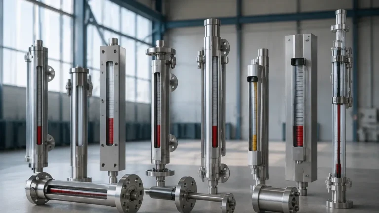
In the landscape of industrial fluid management, the term "xl gauges" typically refers to extended-length or high-capacity magnetic level indicators designed for large-scale storage tanks and process vessels. These instruments are critical components in the B2B sector, particularly within the oil and gas, chemical processing, and water treatment industries, where monitoring liquid levels over significant vertical distances is a daily operational requirement. Unlike standard sight glasses, which can be fragile and limited in height, Magnetic & Local Level Gauges provide a robust, leak-proof solution for high-volume applications.
Selecting the correct xl gauges requires a deep understanding of the mechanical principles involved, the chemical compatibility of the materials, and the structural requirements of the vessel. This guide provides an engineering-focused overview of how these instruments function, their selection criteria, and the practical considerations for their deployment in demanding industrial environments.
Measurement Principles of Magnetic Level Gauges
Before specifying xl gauges for a project, it is essential to understand the underlying physics that allow these instruments to provide accurate, real-time data without the risks associated with direct-contact glass indicators.
The Buoyancy Principle
The fundamental operation of a magnetic level gauge is based on Archimedes' Principle. A float is engineered with a specific density that allows it to remain partially submerged at the surface of the process liquid. As the liquid level in the vessel rises or falls, the float moves accordingly within a bypass chamber (the "column") that is connected to the tank via process flanges.
Magnetic Coupling
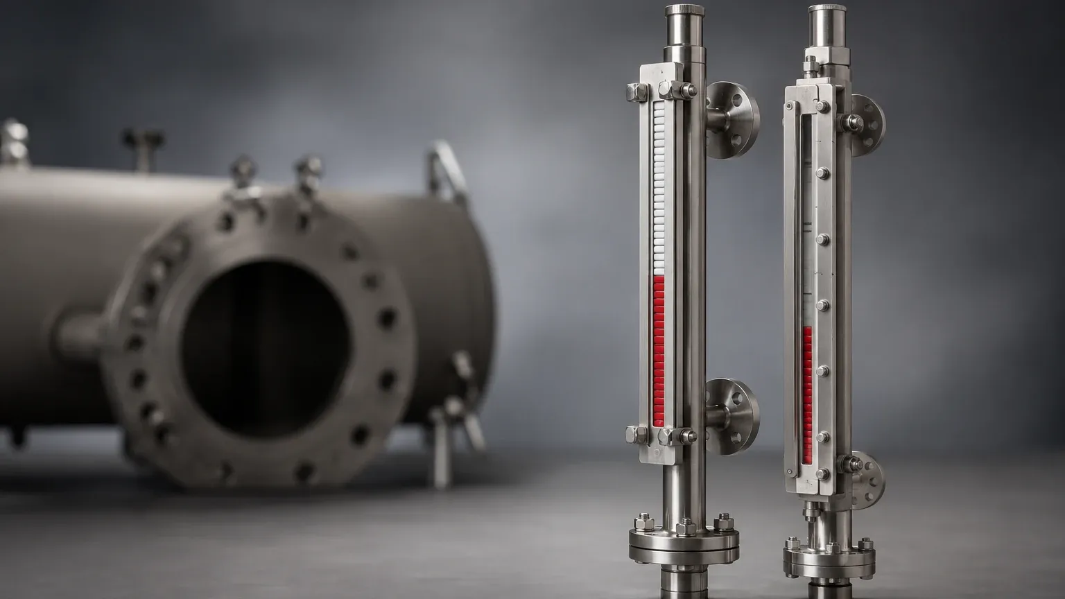
Inside the float is a permanent magnet assembly, usually arranged in a 360° ring to ensure consistent orientation. Outside the chamber, a visual indicator—often consisting of a series of bi-color magnetic flaps or flags—is mounted. As the float moves, its magnetic field acts upon these flags, flipping them to display a different color (typically changing from white to red or yellow). This magnetic coupling ensures that the indicating scale is completely isolated from the process fluid, eliminating the risk of leaks or glass breakage.
Remote Transmission
While xl gauges are primarily local indicators, they are frequently outfitted with reed-chain transmitters or magnetostrictive sensors. these components sense the position of the float and convert it into a 4-20mA signal or a digital output (HART, Modbus), allowing the local gauge to integrate into a centralized Distributed Control System (DCS).
Key Evaluation Criteria for XL Gauges
When dealing with "XL" or extended-length gauges, the engineering challenges increase. Standard gauges might cover 1 to 2 meters (approx. 3.2 to 6.5 feet), but xl gauges may extend to 6 meters (approx. 19.7 feet) or more. This height introduces variables such as float weight, chamber rigidity, and magnetic field strength.
1. Specific Gravity (SG) and Float Design
The float must be lighter than the liquid it displaces. In high-pressure applications, the float must also be strong enough to resist collapsing. For xl gauges used in tall tanks, the float often needs to be larger to house more powerful magnets, which in turn requires a larger diameter bypass chamber. Engineers must confirm the minimum specific gravity of the fluid to ensure the float will not sink.
2. Pressure and Temperature Ratings
Industrial processes often involve extreme conditions. XL gauges must be rated for the maximum allowable working pressure (MAWP) of the vessel. High temperatures can affect the strength of the permanent magnets; therefore, specialized Alnico or high-temperature Samarium-Cobalt magnets may be required for applications exceeding 250°C (482°F).
3. Material Compatibility
The chamber and float are typically constructed from Stainless Steel (304 or 316L). However, for corrosive environments involving acids or seawater, materials like Hastelloy, Monel, or Titanium may be necessary. In some cases, a PTFE (Teflon) lining is applied to the interior of the stainless steel chamber to provide chemical resistance while maintaining structural integrity.
Technical Specifications and Selection Table
Choosing between a standard local indicator and a specialized xl gauge configuration depends on the vessel height and the process complexity. The following table outlines the typical parameters for selecting magnetic level gauges in large-scale applications.
| Feature | Standard Local Gauge | XL (Extended Length) Gauge |
| :— | :— | :— |
| Measuring Range | 0.3m to 3m (1ft to 10ft) | 3m to 12m+ (10ft to 40ft+) |
| Chamber Diameter | 50mm to 60mm (2" to 2.4") | 63mm to 100mm (2.5" to 4") |
| Connection Type | Flanged, Threaded, or Welded | Heavy-duty Flanged (ANSI/DIN) |
| Support Requirements | Self-supporting | Intermediate support brackets required |
| Max Pressure | Up to 4.0 MPa (40 bar) | Up to 25.0 MPa (250 bar) |
| Visual Indicator | Standard Flaps | High-visibility or Wide-flag options |
| Shipping | Single piece | Often shipped in sections for field assembly |
Installation and Maintenance Guidelines
Because xl gauges are physically large and heavy, installation requires more than just bolting a flange. Proper support and alignment are critical to the long-term reliability of the instrument.
Structural Support
For any gauge exceeding 3 meters (approx. 10 feet), intermediate support brackets must be used. These brackets anchor the gauge chamber to the tank wall or a nearby structural frame. This prevents the chamber from vibrating or bending under the weight of the fluid or due to wind loads in outdoor installations.
Alignment and Leveling
The bypass chamber must be installed perfectly vertical. If the chamber is tilted, the float may experience friction against the chamber walls, leading to "stiction" (static friction) where the float gets stuck, resulting in false level readings. Use a precision spirit level or laser alignment tool during the bolting process.
Venting and Draining
Every xl gauge installation should include a vent valve at the top and a drain valve at the bottom. This allows the chamber to be isolated from the vessel for maintenance. Periodically flushing the chamber through the drain valve is necessary to remove sediment or scale that could interfere with float movement.
Commissioning Steps
1. Visual Inspection: Check the chamber for any transport damage or debris.
2. Float Insertion: Ensure the float is inserted with the "Top" marking facing up. Improper orientation will result in the magnets failing to engage the indicator flaps.
3. Gradual Pressurization: Open the process valves slowly to avoid a pressure surge that could damage the float.
Common Risks and Operational Limitations
While xl gauges are highly reliable, they are not universal solutions for every level measurement challenge. Engineers should be aware of the following limitations:
* Magnetic Interference: Large steel structures or high-voltage cables located too close to the gauge can interfere with the magnetic coupling between the float and the indicator.
* Flashing and Boiling: If the liquid in the chamber begins to boil or flash into vapor, the resulting bubbles can cause the float to bounce erratically, leading to "chatter" in the visual indicator and potential damage to the internal magnets.
* Coating and Buildup: In applications involving heavy crude oil or wastewater with high solids content, material can build up on the float or the chamber walls. This increases the weight of the float and can eventually cause it to seize. Regular cleaning intervals must be established for these service types.
* Extreme Vibration: High-vibration environments (e.g., near large pumps or compressors) can cause the magnetic flaps to flip prematurely. In these cases, dampened indicators or magnetic "latches" should be specified.
Frequently Asked Questions (FAQs)
Q: Can xl gauges be used for interface measurement between two liquids?
A: Yes. By weighting the float to a specific density that falls between the specific gravities of the two liquids (e.g., oil and water), the float will sink through the top layer and float on the bottom layer, accurately indicating the interface level.
Q: How do I handle shipping for a gauge that is 10 meters long?
A: Gauges of this length are typically manufactured in sections. They are joined in the field using specialized flange sets or weld-neck connectors. It is vital to ensure the internal transition between sections is smooth to allow the float to pass without obstruction.
Q: Are xl gauges suitable for cryogenic applications?
A: Yes, but they require a vacuum-jacketed chamber or specialized insulation to prevent ice buildup on the indicator, which would otherwise obscure the reading and freeze the magnetic flaps.
Q: What is the benefit of a wide-flag indicator on an XL gauge?
A: On very tall tanks, the gauge is often viewed from a distance or from the ground. Wide-flag indicators increase the surface area of the color-coded flaps, making the level visible from 30 meters (approx. 100 feet) or more.
Conclusion
Implementing xl gauges within an industrial facility requires a balance of mechanical engineering and process knowledge. By focusing on the specific gravity of the media, the structural integrity of the bypass chamber, and the precision of the magnetic coupling, operators can ensure a long-lasting and maintenance-free level measurement solution. For complex projects involving high pressures or extreme heights, consulting with a professional manufacturer like Welk ensures that the Magnetic & Local Level Gauges are customized to meet the exact safety and performance standards of the application.