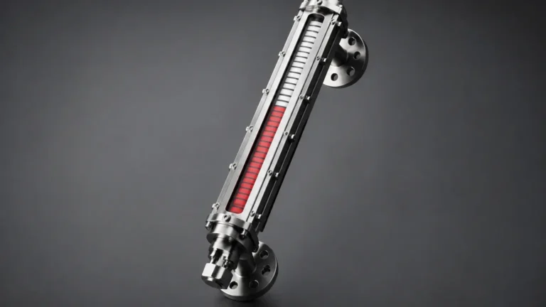
4×4 Level Gauge
4×4 Level Gauge
In industrial process control, the ability to monitor liquid levels locally without relying solely on electronic systems is a critical safety and operational requirement. The 4×4 level gauge, a specialized configuration within the broader category of Magnetic & Local Level Gauges, provides a robust, high-visibility solution for challenging environments. These instruments are engineered to offer clear visual indication in applications ranging from chemical storage to high-pressure steam drums, ensuring that operators can verify tank levels at a glance, even from a distance.
Understanding the engineering behind these gauges is essential for selecting the right equipment for water treatment, oil and gas, or industrial automation projects. This guide explores the principles, selection criteria, and installation requirements for 4×4 level gauges in professional B2B applications.
Measurement Principles of Magnetic Level Gauges
The 4×4 level gauge operates on the fundamental physical principles of buoyancy and magnetism. Unlike traditional glass sight gauges, which expose the process fluid to a fragile glass tube, magnetic gauges utilize a sealed metallic chamber to contain the liquid.
The Buoyancy Component
Inside the vertical chamber (the bypass), a custom-engineered float is designed to match the specific gravity of the process liquid. As the liquid level in the tank rises or falls, the float moves proportionally within the chamber. This float contains a high-intensity internal magnet assembly, typically arranged in a 360° ring to ensure consistent coupling with the external indicator.
Magnetic Coupling and Indication
The "4×4" designation often refers to the high-visibility indicator housing or the ruggedized scale assembly. Mounted to the outside of the chamber is the indication rail. This rail is completely isolated from the process fluid. It contains a series of magnetic flags (flappers) or a magnetic follower (shuttle).
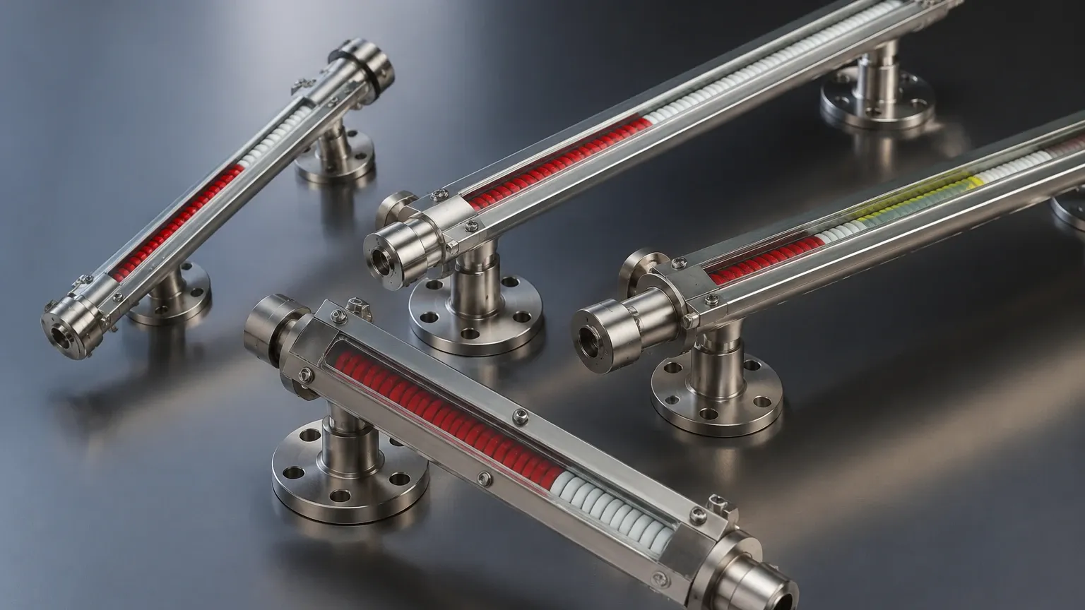
As the float moves, its magnetic field passes through the chamber wall and flips the flags—usually from white to red or silver to red—or moves the follower along a graduated scale. This magnetic coupling ensures that there is no physical leak path, making the 4×4 level gauge an ideal choice for hazardous, toxic, or high-pressure media.
Key Features of the 4×4 Level Gauge Design
When evaluating a 4×4 level gauge for industrial use, several design features distinguish it from standard local indicators. These features focus on durability and readability in harsh outdoor or high-vibration environments.
1. High-Visibility Display: The indicator scale is typically wider than standard models, often featuring large, bold numerals and high-contrast flags. This allows for accurate readings from distances of 15 to 25 meters (approx. 50 to 80 feet).
2. Pressure Boundary Integrity: By using a solid metal chamber (often Stainless Steel 316L, Titanium, or Hastelloy), the gauge acts as a primary pressure vessel. It can withstand pressures that would shatter conventional glass gauges.
3. Environmental Protection: The indication rail is usually sealed within a glass or polycarbonate tube, often IP65 or IP67 rated, to prevent dust, moisture, and corrosive fumes from interfering with the magnetic flags.
4. Redundancy Options: Many 4×4 level gauges are equipped with secondary outputs, such as reed switches for level alarms or magnetostrictive transmitters for 4-20mA remote monitoring, providing both local and control-room data.
Selection Criteria and Technical Specifications
Selecting a 4×4 level gauge requires precise data regarding the process media and the tank geometry. Engineers must confirm the following parameters to ensure the float performs correctly and the chamber remains intact.
Technical Selection Table
| Parameter | Description / Requirement | Typical Range (Standard to High-End) |
| :— | :— | :— |
| Specific Gravity | The density of the liquid at operating temperature. | 0.45 to 2.0 |
| Design Pressure | Maximum pressure the chamber must withstand. | Vacuum to 320 bar (approx. 4640 psi) |
| Design Temperature | Operating temperature of the process fluid. | -196°C to 450°C (-320°F to 842°F) |
| Viscosity | Resistance to flow; affects float movement. | Up to 500 cP (higher with special designs) |
| Center-to-Center | The distance between the mounting flanges. | 300 mm to 6000 mm+ (12" to 236"+) |
| Material | Wetted parts compatibility. | SS316, PVC, PTFE Lined, Monel |
Material Compatibility
For corrosive applications, such as sulfuric acid or brine, the chamber and float must be constructed from or lined with compatible materials. A PTFE-lined stainless steel chamber is a common solution for aggressive chemicals, while titanium floats are used for low-density fluids where high strength-to-weight ratios are required.
Installation and Mounting Best Practices
Proper installation is critical for the long-term reliability of a 4×4 level gauge. Because these instruments rely on a free-moving float, alignment and cleanliness are paramount.
Mounting Configurations
* Side-Side Mounting: The most common configuration, where the gauge is attached to the side of the tank via two nozzles. This allows for easy isolation using valves for maintenance.
* Top-Bottom Mounting: Used when side access is limited. The gauge is connected to the top and bottom of the vessel.
* Top-In (Still Well): If the gauge cannot be mounted externally, a magnetic float can be used inside a stilling well within the tank, with the indicator mounted above the tank head.
Installation Checklist
1. Vertical Alignment: The chamber must be installed perfectly vertical (within 3°). Any tilt can cause the float to rub against the chamber walls, leading to friction and inaccurate readings.
2. Isolation Valves: Always install high-quality isolation valves between the tank and the gauge. This allows the gauge to be drained and serviced without depressurizing the entire vessel.
3. Magnetic Interference: Ensure that there are no large ferrous structures or high-voltage cables within 200 mm (approx. 8 inches) of the gauge, as these can interfere with the magnetic coupling.
4. Venting and Draining: The gauge should be equipped with a vent plug at the top and a drain valve at the bottom to facilitate commissioning and cleaning.
Limitations and Operating Constraints
While the 4×4 level gauge is highly versatile, it is not suitable for every application. Engineers should be aware of the following limitations:
* Build-up and Scaling: If the process fluid is prone to heavy scaling or contains magnetic particles (such as iron filings), these can accumulate on the float or the chamber walls, eventually pinning the float in place.
* Extreme Viscosity: Very thick liquids can slow the response time of the float or cause it to stick. In these cases, heat tracing or insulation blankets may be required to maintain fluid temperature and lower viscosity.
* Specific Gravity Fluctuations: Since the float is weighted for a specific density, significant changes in the liquid's composition or temperature (which changes density) can lead to measurement errors. If the density drops below the float's design limit, the float will sink.
* Flashing and Boiling: Rapid boiling or flashing within the chamber can cause the float to bounce violently, potentially damaging the internal magnet or the indication rail.
Maintenance and Troubleshooting
One of the primary advantages of Magnetic & Local Level Gauges is their low maintenance requirement. However, periodic checks are recommended to ensure accuracy.
Routine Maintenance
* Visual Inspection: Check the indication rail for cracked glass or faded flags. Ensure the scale remains legible.
* Flushing: Periodically open the drain valve to flush out any sediment that may have collected at the bottom of the chamber. This is especially important in water treatment or crude oil applications.
* Float Check: During plant shutdowns, remove the float to inspect for wear, pitting, or build-up. Ensure the internal magnets have not lost their strength (though modern rare-earth magnets are extremely stable).
Troubleshooting Common Issues
* Indicator Stuck: If the flags stop moving while the level is known to be changing, use a handheld magnet to "reset" the flags. If the problem persists, the float may be stuck due to debris.
* Inaccurate Reading: Verify the specific gravity of the process fluid. If the fluid is lighter than the float's design, the gauge will read lower than the actual level.
* Condensation in Indicator: If moisture enters the indication rail, it can fog the display. Check the seals and consider a nitrogen-purged indicator for cryogenic applications.
Frequently Asked Questions (FAQs)
Q: Can a 4×4 level gauge be used for interface measurement (e.g., oil and water)?
A: Yes. By weighting the float to a density between the two liquids (e.g., 0.85 SG), the float will sink through the top layer and float on the bottom layer, effectively indicating the interface level.
Q: What is the maximum height for a single-piece magnetic level gauge?
A: Most manufacturers can produce single-section chambers up to 6 meters (approx. 20 feet). For taller tanks, the gauges are manufactured in sections and joined with flanges or unions.
Q: Do these gauges require power?
A: The basic visual indication is purely mechanical and requires no power. However, if you add a transmitter or limit switches for remote monitoring, those components will require a standard 24V DC loop power.
Q: How do I handle liquids that might freeze or solidify?
A: For such applications, the 4×4 level gauge can be equipped with a steam jacket or electric heat tracing, along with thermal insulation, to keep the process fluid in a liquid state within the chamber.
By following these engineering guidelines and selection criteria, project managers and engineers can implement 4×4 level gauges that provide reliable, maintenance-free local level indication for years of service in demanding industrial environments.