What Are the 4 Gauges
What Are the 4 Gauges
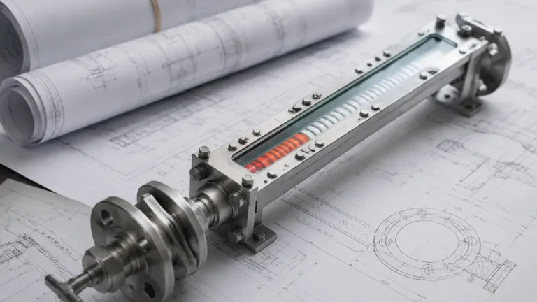
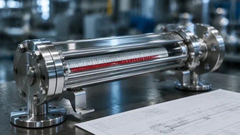
In the landscape of industrial process control, local level measurement remains a cornerstone of safety and operational reliability. While modern facilities rely heavily on remote sensors like radar or ultrasonic transmitters, the physical presence of a local gauge provides a critical "source of truth" for operators on the plant floor. When engineers ask, "what are the 4 gauges?" in the context of level measurement, they are typically referring to the four primary technologies used for direct, visual indication of liquid levels in tanks and pressure vessels.
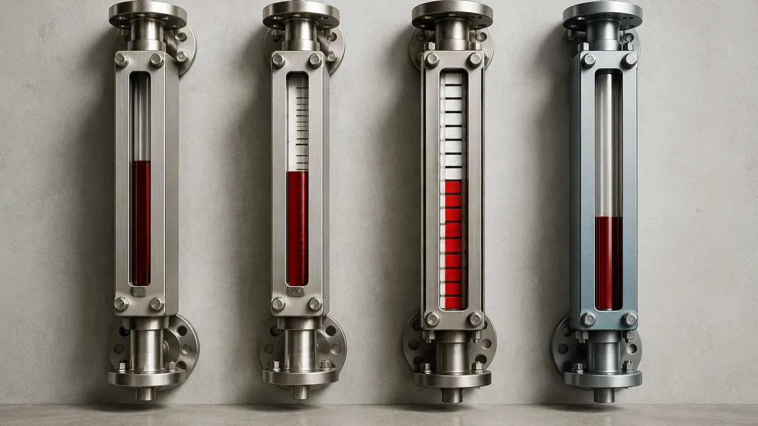
These four gauges—Magnetic Level Gauges, Reflex Glass Gauges, Transparent Glass Gauges, and Tubular Gauges—each operate on distinct physical principles and are suited to specific environmental conditions. Understanding the nuances between them is essential for ensuring plant safety, especially in high-pressure or corrosive chemical environments.
Understanding Local Level Measurement in Industrial Processes
Local level gauges serve as non-electronic indicators that allow personnel to verify the contents of a vessel without needing a control room interface. This redundancy is vital during power outages, commissioning phases, or when calibrating electronic transmitters.
In industries such as oil and gas, water treatment, and chemical processing, the selection of a gauge is dictated by the "process conditions": pressure, temperature, chemical compatibility, and the physical properties of the liquid (such as opacity or viscosity). Before diving into specific recommendations, it is important to understand the mechanical and optical principles that allow these devices to function.
1. Magnetic Level Gauges (MLG)
The Magnetic Level Gauge is widely considered the most robust and versatile of the four types, particularly for hazardous or high-pressure applications. Unlike glass-based gauges, the Magnetic & Local Level Gauges system completely isolates the process fluid from the indicator, eliminating the risk of leaks associated with glass breakage.
Measurement Principle
Magnetic level gauges operate on the principle of buoyancy and magnetic coupling. The device consists of a bypass chamber (a vertical pipe) mounted to the side of the vessel. Inside this chamber is a float containing a high-intensity omnidirectional magnet. As the liquid level in the vessel rises or falls, the float moves accordingly within the chamber.
On the outside of the chamber, a sealed indicator rail is mounted. This rail contains a series of magnetic flags (usually bi-color, such as red and white). As the float moves past these flags, the magnetic field causes them to rotate 180 degrees. This change in color provides a clear, high-contrast visual representation of the liquid level that can be seen from a significant distance.
Advantages and Use Cases
Because the indicator is not in contact with the fluid, MLGs are ideal for toxic, flammable, or corrosive media. They can withstand extreme pressures—often exceeding 200 bar (2900 PSI)—and temperatures ranging from cryogenic levels to over 400°C (752°F). Furthermore, they can be equipped with magnetic switches or transmitters to provide electronic feedback alongside the visual display.
2. Reflex Glass Level Gauges
Reflex glass gauges are the standard choice for clean, non-viscous liquids where a simple, high-contrast visual is required. They are named for the optical principle of light refraction (reflexion) they utilize to distinguish between liquid and vapor.
Measurement Principle
The reflex gauge features a single piece of heavy-duty borosilicate glass with a series of longitudinal prisms (grooves) molded into the side facing the liquid. When light enters the gauge from the front:
1. In the Vapor Zone: The light hits the prisms and is reflected back to the observer. This makes the vapor space appear bright, silvery, or white.
2. In the Liquid Zone: The liquid fills the grooves of the prisms, changing the refractive index. Instead of reflecting, the light is absorbed or transmitted through the liquid. This makes the liquid column appear dark or black.
Limitations
Reflex gauges are highly effective for clear liquids like water or light hydrocarbons. However, they are not suitable for measuring the interface between two liquids (e.g., oil and water), as the refractive change only occurs between gas and liquid. Additionally, they should be avoided in steam applications above 20 bar (290 PSI) or with fluids that can erode the glass prisms, such as high-alkalinity solutions.
3. Transparent Glass Level Gauges
Transparent gauges, also known as "thru-vision" gauges, are designed for applications where the reflex principle fails—specifically for colored liquids, interface measurement, or when the process involves steam.
Measurement Principle
A transparent gauge consists of two pieces of flat borosilicate glass mounted on opposite sides of a metal chamber. This allows light to pass directly through the gauge. To see the level, an illuminator is typically mounted behind the gauge. The operator views the liquid level by observing the actual meniscus or the color difference of the fluid itself.
Specialized Applications
* Interface Measurement: Because you can see through the fluid, transparent gauges are the only glass-type gauges capable of showing the distinct line between two immiscible liquids of different densities.
* Steam Service: In high-pressure steam boilers, transparent glass is often protected by a thin sheet of mica. The mica shield prevents the hot, alkaline boiler water from etching the glass, significantly extending the service life of the gauge.
* Dirty or Viscous Fluids: If a fluid is dark or leaves a residue, the transparent gauge allows for easier visual identification than the reflex type.
4. Tubular Level Gauges
Tubular gauges are the simplest and most cost-effective of the 4 gauges. They are generally reserved for low-pressure, non-hazardous applications where basic visibility is the primary requirement.
Measurement Principle
A tubular gauge consists of a high-strength glass or plastic tube connected directly to the vessel via isolation valves (often called "gauge cocks"). The liquid enters the tube and reaches the same height as the liquid in the tank, following the law of communicating vessels. The level is read directly through the transparent tube.
Constraints and Safety
Due to the exposed nature of the tube, these gauges are vulnerable to mechanical impact. Most industrial tubular gauges are fitted with metal guards or protectors to prevent accidental breakage. They are typically limited to pressures below 10 bar (145 PSI) and temperatures below 100°C (212°F). They are commonly found in water storage tanks, lube oil reservoirs, and non-toxic chemical totes.
Practical Selection Table: Comparing the 4 Gauges
| Feature | Magnetic Level Gauge | Reflex Glass Gauge | Transparent Glass Gauge | Tubular Level Gauge |
| :— | :— | :— | :— | :— |
| Visibility | Excellent (High contrast) | Good (Black/Silver) | Moderate (Requires light) | Good (Direct) |
| Max Pressure | Very High (>200 bar) | Medium (up to 70 bar) | Medium (up to 70 bar) | Low (<10 bar) |
| Max Temp | Very High (>400°C) | Moderate (up to 250°C) | Moderate (up to 280°C) | Low (<100°C) |
| Hazardous Media | Best (Sealed chamber) | Fair (Risk of glass leak) | Fair (Risk of glass leak) | Poor (Exposed tube) |
| Interface Measurement | Yes (with specific float) | No | Yes | Yes |
| Steam Service | Yes | No (Prisms erode) | Yes (with mica shield) | No |
| Relative Cost | High | Medium | Medium-High | Low |
Installation and Engineering Considerations
When implementing any of the 4 gauges, engineers must account for several critical installation factors to ensure accuracy and safety:
1. Isolation and Safety Valves
Every gauge should be installed with isolation valves (ball or needle valves) to allow for maintenance without draining the entire vessel. For glass gauges, "auto-shutoff" ball check valves are recommended. If the glass breaks, the sudden rush of fluid forces a stainless steel ball against a seat, immediately stopping the leak.
2. Venting and Draining
Gauges must be equipped with vent plugs at the top and drain valves at the bottom. This allows the gauge to be safely depressurized and emptied before maintenance. In the case of Magnetic Level Gauges, regular flushing of the chamber via the drain valve prevents the buildup of sediment that could jam the float.
3. Center-to-Center Distance
The most critical measurement during the procurement phase is the "Center-to-Center" (C-C) distance. This is the vertical distance between the two process connections on the tank. For magnetic gauges, the overall length of the chamber will be longer than the C-C distance to allow for a "float well" at the bottom where the float rests when the tank is empty.
4. Specific Gravity (SG)
For Magnetic Level Gauges, the float must be engineered to match the specific gravity of the liquid. If the liquid is lighter than the float's design, the float will sink, providing a false empty reading. If the liquid is significantly heavier, the float will sit too high, causing an offset in accuracy.
Limitations and Common Risks
While these gauges are reliable, they are not without limitations.
* Glass Etching: In glass gauges, certain chemicals (like hydrofluoric acid) or high-temperature steam will chemically attack the borosilicate glass, making it cloudy and eventually weakening it to the point of failure.
* Magnetic Interference: Magnetic level gauges must be kept away from large external magnetic fields or ferrous structures that could interfere with the float-to-flag coupling.
* Coating and Scaling: If the process fluid is prone to scaling or heavy coating, it can cause the float in an MLG to stick or obscure the glass in a reflex/transparent gauge. In these instances, internal liners or specialized coatings may be required.
Frequently Asked Questions (FAQ)
Q: Can I use a Reflex gauge for oil-water interface?
A: No. Reflex gauges rely on the refractive difference between gas and liquid. To see the interface between two liquids, you must use a Transparent gauge or a Magnetic Level Gauge with a float weighted specifically for the interface density.
Q: Why choose a Magnetic Level Gauge over a Transparent one for high-pressure steam?
A: While transparent gauges with mica shields work for steam, Magnetic Level Gauges are often preferred because they eliminate the maintenance burden of replacing mica and glass. They also provide better visibility from the plant floor.
Q: What is the maximum length for these gauges?
A: Glass gauges are usually limited to sections of about 300mm to 500mm to prevent glass breakage. For longer ranges, multiple sections are "stacked." Magnetic Level Gauges can be manufactured in single continuous lengths of up to 6 meters (approx. 20 feet) or more.
Q: Do these gauges require power?
A: No. All four types are purely mechanical/optical. However, Magnetic Level Gauges can be retrofitted with reed switches or 4-20mA transmitters if electronic integration is needed later.
Conclusion
Selecting the right instrument from the 4 gauges depends entirely on the balance between safety requirements, process conditions, and budget. For high-risk, high-pressure environments, the Magnetic Level Gauge offers unparalleled safety by isolating the fluid. For simpler, visual-heavy tasks, Reflex and Transparent gauges provide direct sight of the process, while Tubular gauges remain the go-to for basic, low-pressure utility applications.
By understanding the measurement principles and limitations of each, engineers can ensure that their local level indication is both accurate and durable, providing a reliable backup to the plant's automated systems.