Capacitance Level Sensor
Capacitance Level Sensor
Capacitance level sensors represent one of the most versatile and established technologies in the field of industrial level measurement. Used extensively across industries such as water treatment, chemical processing, and oil and gas, these sensors provide a reliable method for monitoring both liquid and solid levels. As a professional manufacturer, Welk specializes in providing robust measurement solutions that integrate seamlessly into complex industrial automation systems. This guide provides a detailed technical overview of capacitance level sensors, their operating principles, selection criteria, and practical installation requirements.
Understanding the Measurement Principle of Capacitance Level Sensors
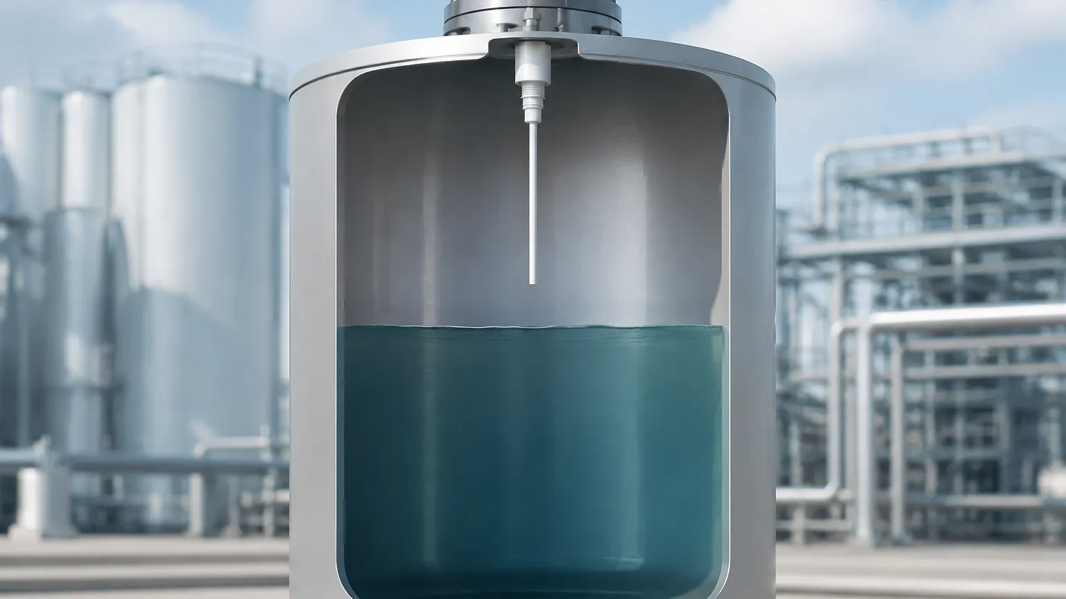
The operation of a capacitance level sensor is rooted in the basic physical principles of a capacitor. In an industrial tank, the measurement system typically consists of two conductive plates separated by an insulating material known as a dielectric. In most applications, the sensor probe acts as one plate of the capacitor, while the conductive tank wall (or a secondary reference ground rod) acts as the second plate.
The ability of this setup to store an electrical charge is defined as capacitance ($C$), which is determined by the formula:
$$C = \epsilon \cdot (A / d)$$
Where:
* $\epsilon$ (Epsilon): The permittivity (dielectric constant) of the material between the plates.
* A: The surface area of the plates.
* d: The distance between the plates.
* C: Capacitance in Farads.
In level measurement applications, the surface area ($A$) and the distance ($d$) remain constant once the sensor is installed. Therefore, the capacitance becomes a direct function of the dielectric constant ($\epsilon$) of the medium between the probe and the tank wall.
Air has a relative dielectric constant ($Er$) of approximately 1.0. Most industrial process materials have a significantly higher dielectric constant (e.g., mineral oil $\approx$ 2.0, plastic pellets $\approx$ 1.1 to 3.0, and water $\approx$ 80). As the level of the material rises in the tank, it displaces the air, changing the total permittivity of the space. This change in capacitance is processed by the sensor's electronics and converted into a proportional 4-20mA signal, a frequency output, or a digital communication protocol representing the level.
Conductive vs. Non-Conductive Media
The measurement approach differs slightly depending on the electrical conductivity of the medium:
1. Non-Conductive Media: For materials like oils or dry powders, a standard non-insulated probe can often be used. The material itself acts as the dielectric.
2. Conductive Media: For water-based liquids or acids, the material would short-circuit an exposed probe. In these cases, the probe is coated with an insulating layer (such as PTFE or PFA). The insulation acts as the dielectric, and the conductive liquid acts as the second plate of the capacitor.
Continuous vs. Point Level Capacitance Measurement
Capacitance technology is applicable for both continuous level monitoring and point level detection (switching).
Continuous Level Sensors
Continuous sensors provide a real-time tracking of the level from 0% to 100%. They are ideal for inventory management and process control where precise volume data is required. These sensors typically use long rods for shallow tanks (up to 3 or 4 meters) or flexible cables for deep silos and tall tanks (up to 30 meters or more).
Capacitance Level Switches
Point level switches are used to detect the presence or absence of material at a specific height. They are commonly used for high-level alarm (overfill protection) or low-level alarm (pump dry-run protection). These devices are generally more compact and are designed to ignore minor build-up on the probe through advanced electronic compensation.
Key Factors for Selecting a Capacitance Level Sensor
Selecting the correct sensor requires a thorough understanding of the process environment. The following table provides a comparison of common configurations based on the material being measured.
Selection Table: Probe Configurations
| Medium Type | Conductivity | Recommended Probe Type | Typical Applications |
| :— | :— | :— | :— |
| Clean Liquids | Low (Non-conductive) | Uninsulated Rod/Cable | Fuel tanks, hydraulic oil, solvents |
| Water-based Liquids | High (Conductive) | Fully Insulated (PTFE/PFA) | Water treatment, cooling towers, acids |
| Dry Solids/Powders | Very Low | Heavy-duty Uninsulated Rod | Grain silos, plastic resin, cement |
| Corrosive Chemicals | High | Specialized Chemical-Resistant Insulation | Chemical storage, pickling tanks |
| High Temperature | Variable | Ceramic Insulated Probes | Steam boilers, hot oil processing |
Evaluation Criteria
When evaluating a capacitance level sensor for your facility, consider the following technical specifications:
* Dielectric Constant ($Er$): The material must have a stable $Er$. If the $Er$ fluctuates significantly (e.g., due to temperature or composition changes), the accuracy of the sensor may be affected unless a compensation probe is used.
* Tank Material: If the tank is non-conductive (e.g., plastic or fiberglass), a dual-probe sensor or a grounding strap is required to provide the second "plate" for the capacitor.
* Pressure and Temperature: Standard sensors handle up to 100°C and 20 bar, but specialized versions are available for extreme environments reaching 400°C or high-pressure reactors.
* Vessel Geometry: Internal obstructions like agitators or baffles can interfere with the electromagnetic field of the probe. Proper clearance must be maintained.
For more detailed technical specifications and to explore various industrial level measurement instruments, you can visit the Main Page of our product catalog.
Installation Considerations and Best Practices
Proper installation is critical to the longevity and accuracy of a capacitance level sensor. Engineers should adhere to the following guidelines during the design and commissioning phases:
1. Avoid Proximity to Walls: The probe should be installed at a distance from the tank wall to prevent interference, typically at least 100 mm to 200 mm depending on the probe length. However, it must remain parallel to the wall if the wall is being used as the reference ground.
2. Grounding: Ensure a low-resistance electrical connection between the sensor housing and the metal tank. For non-metallic tanks, a reference rod must be installed alongside the measurement probe.
3. No-Go Zones: Do not install the sensor directly in the path of the material inflow. The turbulence and physical impact can damage the probe or cause erratic readings. Use a stilling well if high turbulence is unavoidable.
4. Cable Entry: Always point cable entries downward to prevent moisture from entering the housing via capillary action along the wiring.
5. Thread and Flange Integrity: Use appropriate sealants or gaskets compatible with the process media to prevent leaks, especially in pressurized vessels.
Limitations and Managing Operational Risks
While capacitance level sensors are highly effective, they are not universal solutions. Understanding their limitations helps in mitigating operational risks.
* Material Build-up: Conductive coatings or sticky residues on the probe can lead to false readings, as the sensor may "see" the build-up as the actual level. Modern sensors utilize "active shield" technology to ignore the capacitance of the build-up near the mounting nozzle.
* Changing Dielectric Constants: If a tank is used for different liquids with varying $Er$ values, the sensor will require recalibration for each new material. In such cases, radar or hydrostatic transmitters might be more suitable.
* Moisture Content in Solids: In bulk solids, changes in moisture content significantly alter the dielectric constant, which can introduce errors in continuous level measurement.
* Foam: Dense, conductive foam can be detected as a liquid level, which may or may not be desirable depending on the application. If foam rejection is required, frequency-shift or ultrasonic technologies may be preferred.
Frequently Asked Questions (FAQ)
Q: Can a capacitance level sensor be used in a plastic tank?
A: Yes, but since the plastic wall is non-conductive, it cannot act as the second plate of the capacitor. You must use a sensor with a ground tube (concentric probe) or install a separate metallic ground rod parallel to the measurement probe.
Q: What is the minimum dielectric constant required for measurement?
A: Most high-quality capacitance sensors can detect materials with a dielectric constant as low as 1.2 to 1.5. For materials lower than this, specialized high-sensitivity electronics are required.
Q: How often does a capacitance sensor need calibration?
A: Under stable process conditions, these sensors are very stable. Recalibration is usually only necessary if the material composition changes significantly or if the probe is replaced. Many modern units feature digital calibration that can be performed at two points (empty and full).
Q: Is it possible to cut the probe to length in the field?
A: Some rod and cable probes are designed to be field-cuttable. However, if the probe is fully insulated (for conductive media), cutting it will destroy the insulation integrity. Always confirm with the manufacturer's data sheet before attempting to modify a probe.
Conclusion
Capacitance level sensors offer a cost-effective, durable, and accurate solution for a wide array of industrial level measurement challenges. By understanding the relationship between the dielectric constant of the media and the sensor's electronic response, engineers can select the most appropriate probe configuration for their specific needs. Whether managing water treatment facilities or monitoring chemical storage, these sensors provide the data necessary for safe and efficient operations.
For professional guidance on selecting the right instrument for your application, or to review our full range of radar, ultrasonic, and hydrostatic solutions, please visit our Main Page. Our team at Welk is committed to providing high-quality, customized level measurement technology to meet the rigorous demands of global industrial automation.