Vega Health
Vega Health
In the landscape of modern industrial automation, the term "Vega health" refers to the operational integrity, diagnostic status, and performance reliability of level measurement instrumentation. In process industries such as chemical manufacturing, water treatment, and oil and gas, maintaining the "health" of a sensor is critical to ensuring plant safety, inventory accuracy, and operational efficiency. This guide explores the technical foundations of level measurement, the diagnostic parameters that define sensor health, and the practical considerations for selecting and maintaining these essential instruments.
Understanding Industrial Level Measurement Principles
Before evaluating the health or performance of a specific system, it is essential to understand the underlying physical principles that govern level measurement. Different technologies interact with the process medium in unique ways, and their "health" is often measured by how well they manage these interactions.
Radar Level Measurement (Time of Flight)
Radar level meters, particularly those operating at high frequencies like 80 GHz, utilize the Time of Flight (ToF) principle. The sensor emits a high-frequency microwave signal toward the medium. This signal reflects off the surface of the product and returns to the antenna. The instrument measures the time elapsed between emission and reception.
Sensor health in radar systems is primarily determined by the signal-to-noise ratio. A "healthy" radar sensor maintains a clear distinction between the actual level reflection (the target echo) and parasitic reflections caused by tank internals like agitators or ladders.
Ultrasonic Level Measurement
Ultrasonic sensors function similarly to radar but use sound waves instead of electromagnetic waves. The transducer emits an ultrasonic pulse that travels through the air gap, reflects off the liquid or solid surface, and returns. Because the speed of sound is influenced by air temperature, healthy ultrasonic systems must include integrated temperature compensation to maintain accuracy.
Hydrostatic Level Measurement
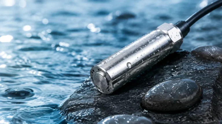
Hydrostatic transmitters measure the pressure exerted by a liquid column. The principle is based on the formula $P = \rho gh$ (Pressure = Density × Gravity × Height). In this context, sensor health relates to the integrity of the sensing diaphragm and the stability of the pressure cell against drift or clogging.
Magnetic Level Gauges and Switches
Magnetic gauges utilize a float containing a permanent magnet that moves with the liquid level. This magnet actuates a visual indicator or a series of reed switches. Health monitoring for these mechanical-electrical hybrid systems involves checking for float buoyancy and the mechanical freedom of the moving parts.
The Role of Diagnostic Data in Sensor Health
Modern industrial sensors, such as those provided by Welk, incorporate advanced self-diagnostic suites. "Vega health" in a digital context often involves the continuous monitoring of several key internal variables:
1. Signal Strength (Amplitude): For radar and ultrasonic sensors, the amplitude of the reflected signal (measured in decibels, dB) is a primary indicator of health. A declining signal strength may indicate foam buildup, heavy condensation on the antenna, or a change in the dielectric constant of the medium.
2. Echo Curve Analysis: Digital level meters provide a visual representation of all reflections within a vessel. A healthy echo curve shows a sharp, distinct peak at the product surface. Distortions in this curve can signal the need for maintenance before a total signal loss occurs.
3. Zero-Point Stability: In hydrostatic and pressure-based systems, health is monitored by checking the zero-point calibration. Drift in the zero point can indicate diaphragm fatigue or chemical attack.
4. Electronic Self-Tests: Internal microprocessors regularly check the integrity of the RAM, ROM, and signal processing circuits. Any discrepancy triggers a fault current (typically 3.6 mA or 21 mA in a 4-20mA loop) to alert the control system.
Evaluation Criteria for Level Measurement Systems
When assessing the health and suitability of a level measurement solution for a specific application, engineers must evaluate several technical criteria. For a broader look at technical specifications and product ranges, professionals often refer to the Main Page of specialized manufacturers to compare performance data.
Media Properties
The dielectric constant ($ε_r$) of the medium is the most critical factor for radar health. Low dielectric materials (like oils or liquefied gases) reflect less energy, requiring higher sensitivity and more robust diagnostic monitoring. For ultrasonic sensors, the presence of dust, steam, or foam can attenuate sound waves, potentially compromising the sensor's "health" or reliability.
Process Conditions
Temperature and pressure extremes directly impact sensor longevity. A sensor operating at its maximum rated temperature of 200°C (392°F) will require more frequent health checks than one operating at ambient temperatures. Similarly, vacuum applications can affect the propagation of sound, making radar a healthier choice for those environments.
Accuracy Requirements
In custody transfer applications, a healthy sensor must maintain sub-millimeter accuracy. In simple pump control applications, a margin of error of 10 mm (0.4 inches) might be acceptable. The health monitoring system should be calibrated to the specific accuracy demands of the process.
Technology Selection Table
The following table provides a comparison of common level measurement technologies and the factors that influence their operational health.
| Technology | Ideal Media | Measurement Range | Key Health Indicator | Sensitivity to Environment |
| :— | :— | :— | :— | :— |
| 80 GHz Radar | Liquids, Solids, Corrosives | Up to 120m (393 ft) | Signal-to-Noise Ratio | Low (Very Robust) |
| Ultrasonic | Water, Wastewater | Up to 15m (49 ft) | Echo Quality/Temp | High (Affected by Wind/Steam) |
| Hydrostatic | Clean Liquids | 1m – 200m (3.2 – 656 ft) | Zero-Point Drift | Medium (Affected by Density) |
| Guided Wave Radar | Low Dielectric Liquids | Up to 75m (246 ft) | Interface Signal | Low (Robust) |
| Magnetic Gauge | Hazardous Chemicals | Up to 6m (20 ft) | Float Buoyancy | Low (Mechanical Reliability) |

Installation Best Practices for Optimal Signal Health
The long-term health of a level meter is often determined during the installation phase. Improper mounting is the leading cause of "unhealthy" sensor readings and premature failure.
Nozzle Geometry
For radar and ultrasonic sensors, the nozzle should be as short and wide as possible. A long, narrow nozzle creates "ringing" or internal reflections that can mask the true product level. Ideally, the antenna or transducer should extend slightly past the bottom of the nozzle into the vessel.
Obstruction Avoidance
Sensors should be installed away from the filling stream and internal structures like agitators, heating coils, or baffles. If an obstruction is unavoidable, many modern sensors allow for "False Signal Suppression," where the instrument learns the location of static obstacles and ignores their reflections. Maintaining the health of this suppression map is vital for consistent performance.
Alignment and Leveling
The sensor must be mounted perpendicular to the product surface. Even a few degrees of tilt can significantly reduce the amount of energy reflected back to the antenna, leading to a weak signal and poor sensor health status.
Environmental Protection
While many industrial sensors are rated IP66/IP67 or IP68, providing a sunshade or protective cover can extend the electronic life of the unit by reducing thermal cycling and UV exposure. Ensuring the cable glands are properly tightened and pointed downward prevents moisture ingress, which is a common cause of terminal health failure.
Common Risks and Limitations in Level Monitoring
Even with the best technology, certain conditions pose risks to the health of the measurement system:
* Build-up and Coating: In sticky or crystallizing media, material can accumulate on the sensor face. While radar can often "see through" thin layers of build-up, heavy coating will eventually attenuate the signal. Sensors with self-cleaning air purges or non-contact designs are preferred in these scenarios.
* Turbulence and Foam: Rapidly moving surfaces or thick foam layers can absorb or scatter signals. In these cases, the sensor health might report a "Loss of Echo." Utilizing a stilling well or bypass pipe can provide a calm surface for accurate measurement.
* Chemical Compatibility: The wetted parts (PTFE, PFA, Stainless Steel, etc.) must be compatible with the process media. Chemical attack on a diaphragm or seal will lead to catastrophic sensor failure.
Frequently Asked Questions (FAQ)
Q: How often should I check the health of my level sensor?
A: For critical safety or control loops, continuous digital monitoring via HART, Profibus, or Foundation Fieldbus is recommended. For general applications, a physical inspection and echo curve verification should be performed annually.
Q: Can a radar sensor's health be affected by changes in the gas phase?
A: Standard atmospheric changes have negligible impact on radar. However, high-pressure vapors (like high-pressure steam) can slightly slow down the microwave signal, requiring a compensation factor to maintain health and accuracy.
Q: What does a "Low Signal" alert mean?
A: This typically indicates that the reflection from the product is becoming difficult for the sensor to distinguish from background noise. This could be due to foam, surface turbulence, or heavy condensation on the sensor lens.
Q: Is it possible to monitor sensor health remotely?
A: Yes, most modern transmitters support Bluetooth or cloud-based diagnostics, allowing technicians to check the health of a sensor from a smartphone or a central control room without climbing the tank.
Conclusion and Next Steps
Maintaining "Vega health"—the peak operational state of your level measurement instruments—requires a combination of choosing the right technology, ensuring precise installation, and utilizing modern diagnostic tools. By understanding the principles of radar, ultrasonic, and hydrostatic measurement, and by monitoring key indicators like signal strength and echo curves, plant operators can prevent unplanned downtime and ensure process safety.
For engineers looking to specify new equipment or upgrade existing systems, reviewing the latest technical data on the Main Page is the first step toward building a robust and healthy level monitoring infrastructure. Proper selection today ensures the long-term health of your process tomorrow.