Water Pressure Transducer
Water Pressure Transducer
In industrial automation and process control, the water pressure transducer serves as a fundamental component for monitoring fluid dynamics and storage levels. While the term is often used interchangeably with "pressure transmitter," a transducer specifically refers to the sensing element that converts mechanical pressure into an electrical signal. In the context of level measurement, these devices utilize the hydrostatic principle to determine the height of a liquid column based on the weight of the fluid above the sensor.
For engineers and facility managers, selecting the correct water pressure transducer requires an understanding of fluid physics, material science, and electrical interfacing. This guide provides a technical overview of how these instruments function, their various configurations, and the critical factors involved in their integration into industrial systems.
Understanding the Hydrostatic Principle
The primary method by which a water pressure transducer measures level is through hydrostatic pressure. This principle states that the pressure at a specific point within a static liquid is directly proportional to the height of the liquid column above that point, provided the density of the liquid remains constant.
The mathematical relationship is expressed as:
P = ρ · g · h
Where:
* P is the hydrostatic pressure (measured in Pascals or Bar).
* ρ (rho) is the density of the liquid (e.g., approximately 1,000 kg/m³ for pure water).
* g is the acceleration due to gravity (standardized at 9.81 m/s²).
* h is the height of the liquid column (meters).
Because gravity and the density of water are generally known constants in a controlled environment, the pressure measured by the transducer can be accurately converted into a linear level reading. For example, in a tank of water, every 1 meter (3.28 feet) of depth equates to approximately 9.81 kPa (1.42 PSI) of pressure.
Gauge vs. Absolute Pressure
In most industrial level applications, a "gauge" water pressure transducer is used. This type of sensor is vented to the atmosphere via a small tube inside the cable, allowing it to cancel out changes in barometric pressure. If the sensor were not vented, a drop in atmospheric pressure (such as during a storm) would be incorrectly interpreted as a drop in water level.
Types of Water Pressure Transducers for Industrial Use
Depending on the installation environment and the physical constraints of the vessel, transducers are typically categorized into two main mechanical designs: submersible and external.
1. Submersible Level Transducers
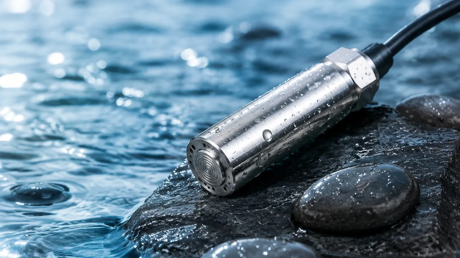
These are designed to be lowered directly into the medium. The sensor is housed in a waterproof, hermetically sealed casing (usually 316L stainless steel or specialized plastics like PVDF for corrosive liquids). The electrical cable includes a reinforced strength member and a capillary tube for atmospheric venting.
* Applications: Deep wells, boreholes, open reservoirs, and wastewater lift stations.
* Advantages: Easy to install in existing tanks without bottom-entry ports; unaffected by surface foam or turbulence.
2. Externally Mounted Transducers
These sensors are mounted to the outside of a tank or pipe via a threaded connection (e.g., NPT or G thread) or a flange. They measure the pressure at the bottom of the vessel through a process connection.
* Applications: Closed pressurized tanks, chemical processing vessels, and pump discharge monitoring.
* Advantages: Easier to maintain as the sensor is not submerged; suitable for high-temperature fluids where the electronics need to be isolated from the heat.
Key Selection Criteria for Engineering Specifications
When specifying a water pressure transducer for a project, several technical parameters must be confirmed to ensure long-term reliability and accuracy. For a broader look at how these sensors fit into a complete instrumentation strategy, engineers often refer to the Main Page of industrial equipment providers to compare hydrostatic options against radar or ultrasonic alternatives.
Measurement Range and Overpressure
The range should be selected so that the maximum expected water level sits at approximately 75% to 80% of the sensor’s full scale. This provides a buffer for unexpected surges. Additionally, the "overpressure rating" defines the maximum pressure the sensor can withstand before mechanical failure occurs.
Material Compatibility
While standard water is non-corrosive, industrial "water" often contains additives, salts, or chemicals.
* 316L Stainless Steel: Standard for clean water and mild chemicals.
* Ceramic Diaphragms: Highly resistant to abrasion and many corrosive agents.
* Titanium: Required for seawater or high-chloride environments to prevent pitting corrosion.
Output Signals and Communication
In modern industrial automation, the transducer must communicate with a PLC (Programmable Logic Controller) or SCADA system. Common outputs include:
* 4-20mA Current Loop: The industry standard for long-distance transmission, as it is resistant to electrical noise.
* 0-10V DC: Common in HVAC and building automation systems.
* Modbus RTU (RS485): A digital protocol that allows for multiple sensors on a single bus and provides diagnostic data.
Comparison Table: Submersible vs. External Sensors
| Feature | Submersible Transducer | External/Threaded Transducer |
| :— | :— | :— |
| Installation Point | Top-down (dropped into liquid) | Side or bottom (threaded port) |
| Maintenance | Requires pulling the cable up | Requires draining the pipe/tank or using a valve |
| Venting | Integrated capillary tube in cable | Vented through the housing |
| Typical Accuracy | 0.25% to 0.5% FS | 0.1% to 0.5% FS |
| Primary Use Case | Reservoirs, Wells, Sumps | Pressurized tanks, Inline pipes |
| Protection Rating | IP68 (Permanent submersion) | IP65/IP67 (Dust/Splash proof) |
Installation Best Practices and Considerations
Proper installation is critical to prevent signal drift and mechanical damage. For any water pressure transducer, the following engineering guidelines should be followed:
Avoiding Turbulence and Physical Damage
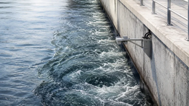
If the transducer is installed in a tank with an agitator or near an inlet pipe, the moving fluid can create localized pressure fluctuations (dynamic pressure) that do not reflect the actual static level. In these cases, a "stilling well" (a perforated pipe) should be used to shield the sensor from turbulent flow.
Cable Management
For submersible models, the cable is a critical component. It should be secured with a cable clamp to prevent the weight of the sensor from straining the electrical connections. Furthermore, the end of the venting tube must be protected from moisture. If water vapor enters the capillary tube, it can condense and block the reference pressure, leading to significant measurement errors. Desiccant cartridges are often used at the termination point to keep the vent dry.
Lightning and Surge Protection
Because water pressure transducers are often used in outdoor reservoirs or deep wells, they are susceptible to induced surges from lightning strikes. Using a transmitter with integrated surge protection or installing an external surge arrestor in the control panel is highly recommended for infrastructure projects.
Limitations and Potential Error Sources
While hydrostatic measurement is reliable, it is not a "fit and forget" solution for every application. Engineers must account for the following limitations:
1. Density Variations: Since the sensor measures weight, any change in the density of the liquid will change the level reading. If a tank is filled with water at 20°C and then heated to 80°C, the water expands and the density drops. The transducer will report a lower level even if the mass of the water remains the same.
2. Pressurized Vessels: In a closed tank with a pressurized gas blanket (such as nitrogen), a single water pressure transducer at the bottom will measure the sum of the liquid pressure and the gas pressure. To solve this, a differential pressure (DP) transmitter is required to subtract the top gas pressure from the total bottom pressure.
3. Sedimentation: In wastewater or mining applications, silt and sludge can accumulate around the sensor diaphragm. This can lead to "clogging," where the sensor becomes unresponsive to level changes. Flush-diaphragm designs or regular cleaning cycles are necessary in these environments.
Frequently Asked Questions (FAQ)
Q: How often should a water pressure transducer be calibrated?
A: For most industrial applications, an annual calibration check is standard. However, in critical water treatment processes, a six-month interval may be required to account for potential sensor drift.
Q: Can I cut the cable of a submersible transducer to fit my tank?
A: Most cables can be shortened, but it must be done carefully to avoid blocking the internal vent tube. It is usually better to specify the required length at the time of order or to coil the excess cable neatly at the top of the tank.
Q: What is the difference between a transducer and a transmitter?
A: Technically, a transducer converts pressure to a low-level electrical signal (like millivolts), while a transmitter conditions that signal into a standardized industrial format like 4-20mA. In modern B2B catalogs, the term "water pressure transducer" is frequently used to describe the complete, field-ready transmitter unit.
Q: How do I protect the sensor from freezing?
A: If the water freezes around the diaphragm, the expansion of ice can permanently deform or crack the sensing element. Transducers should be installed below the frost line in wells or equipped with heat-trace systems in outdoor tanks.
By following these technical guidelines and selecting the appropriate hardware for the specific fluid properties of the site, engineers can ensure that their water pressure transducer provides accurate and maintenance-free service for years. For detailed product specifications and comparative technology data, visiting the Main Page of a specialized manufacturer is the recommended next step in the procurement process.