Differenzdruckverfahren
Differenzdruckverfahren
In the landscape of industrial process control, the measurement of liquid levels is critical for safety, inventory management, and process efficiency. Among the various technologies available, the differenzdruckverfahren (differential pressure method) remains one of the most versatile and widely implemented techniques. This method leverages the fundamental relationship between the height of a liquid column and the hydrostatic pressure it exerts at the base of a vessel.
For engineers and plant operators, understanding the nuances of the differenzdruckverfahren is essential for selecting the right instrumentation and ensuring long-term measurement accuracy. This guide provides a technical overview of the principles, application scenarios, and practical considerations for deploying differential pressure level measurement in modern industrial environments.
Fundamental Principles of Differential Pressure Level Measurement
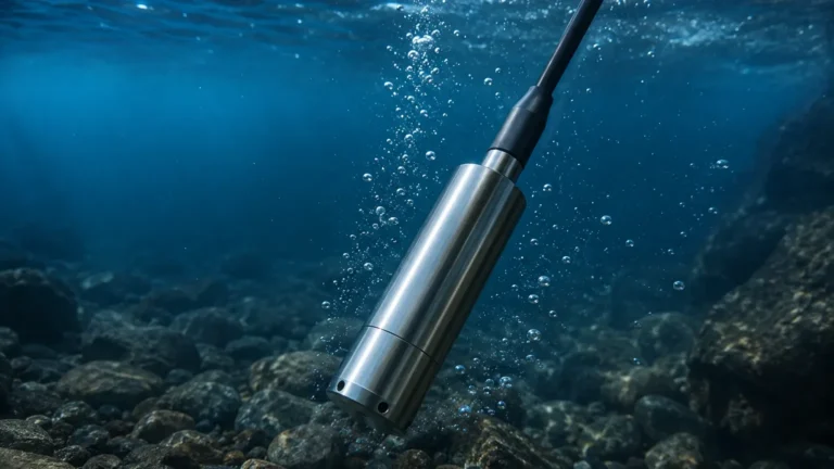
The differenzdruckverfahren operates on the principle of hydrostatic pressure. According to Pascal’s Law, the pressure exerted by a static liquid column is proportional to the height of the column, the density of the liquid, and the force of gravity.
The mathematical formula used to calculate the level ($h$) is:
$$P = \rho \cdot g \cdot h$$
Where:
* $P$ is the hydrostatic pressure (typically measured in Pascals or bar).
* $\rho$ (rho) is the density of the process medium ($kg/m^3$).
* $g$ is the acceleration due to gravity (approximately $9.81 m/s^2$).
* $h$ is the height of the liquid column ($m$).
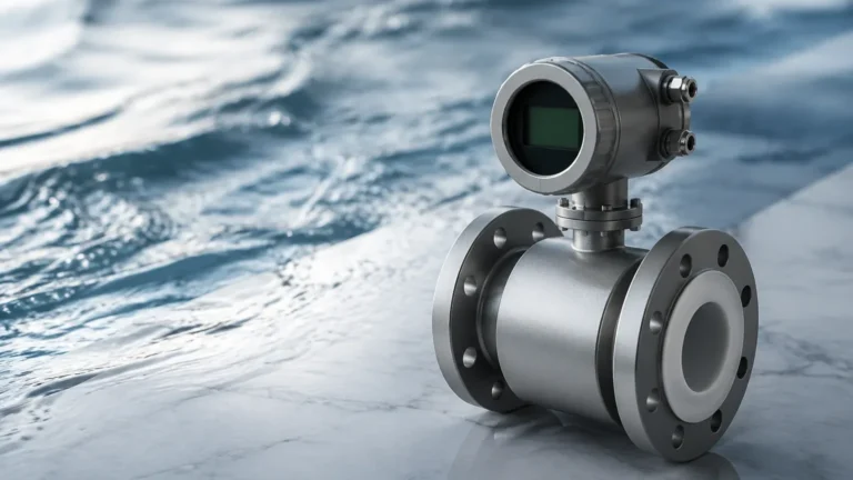
In a differential pressure setup, the transmitter measures the difference between two pressure points. For a level application, the "high-pressure" side is typically connected to the bottom of the tank, while the "low-pressure" side serves as a reference. By calculating the difference between these two points, the system can isolate the pressure generated specifically by the liquid height, effectively cancelling out any superimposed vapor space pressure.
Application in Open vs. Closed Vessels
The implementation of the differenzdruckverfahren varies significantly depending on whether the vessel is vented to the atmosphere or pressurized.
Open (Vented) Vessels
In an open tank, the surface of the liquid is exposed to atmospheric pressure. To measure the level, only the high-pressure side of the transmitter is connected to the bottom of the vessel. The low-pressure side is left open to the atmosphere. In this configuration, the transmitter directly measures the hydrostatic head of the liquid. Any change in atmospheric pressure affects both the liquid surface and the reference side of the sensor equally, thus self-compensating for weather-related pressure shifts.
Closed (Pressurized) Vessels
In closed systems, such as boilers or chemical reactors, the space above the liquid is often filled with pressurized gas or vapor. This internal pressure adds to the hydrostatic pressure at the bottom. To obtain an accurate level reading, the differenzdruckverfahren requires the low-pressure side of the transmitter to be connected to the top of the vessel (the vapor space).
There are two primary ways to manage the reference leg in closed vessels:
1. Dry Leg: Used when the gas in the vapor space will not condense at ambient temperatures. The reference pipe remains filled with gas.
2. Wet Leg: Used when vapors are likely to condense into liquid within the reference line. The reference leg is intentionally pre-filled with a known liquid (often the process fluid or a stable seal fluid) to provide a constant, predictable head pressure that is then mathematically subtracted from the total pressure reading.
Selection Criteria and Comparison Table
Choosing the differenzdruckverfahren over alternative technologies like radar or ultrasonic sensors depends on the specific process conditions. While DP transmitters are highly reliable, they are "intrusive" in the sense that they require process connections (taps) and are sensitive to changes in fluid density.
| Feature | Differenzdruckverfahren (DP) | Radar (Non-Contact) | Ultrasonic |
| :— | :— | :— | :— |
| Measurement Principle | Hydrostatic Pressure | Time-of-Flight (Microwaves) | Time-of-Flight (Sound) |
| Accuracy | High (0.075% to 0.04% of span) | Excellent | Moderate |
| Density Sensitivity | High (Requires constant density) | None | None |
| Pressure Range | Very High (up to 400+ bar) | High | Low to Moderate |
| Temperature Range | Wide (with diaphragm seals) | Very Wide | Limited by air speed/temp |
| Installation Cost | Moderate | High | Low |
| Maintenance | Medium (Impulse line cleaning) | Low | Low |
| Best Use Case | High-pressure boilers, clean liquids | Corrosive chemicals, solids | Water treatment, sumps |
For a comprehensive overview of available technologies and specific product specifications, engineers should consult the Main Page of professional instrumentation providers to match sensor capabilities with chemical compatibility and pressure ratings.

Installation and Engineering Considerations
The accuracy of the differenzdruckverfahren is heavily dependent on the quality of the installation. Unlike non-contact methods, DP measurement involves physical piping (impulse lines) which can introduce errors if not managed correctly.
1. Transmitter Positioning
The DP transmitter should ideally be located below the high-pressure tap for liquid applications. This ensures that the impulse lines remain filled with liquid and that any gas bubbles can migrate back into the tank. Conversely, for gas applications, the transmitter should be located above the taps to allow condensate to drain back into the process.
2. Diaphragm Seals (Remote Seals)
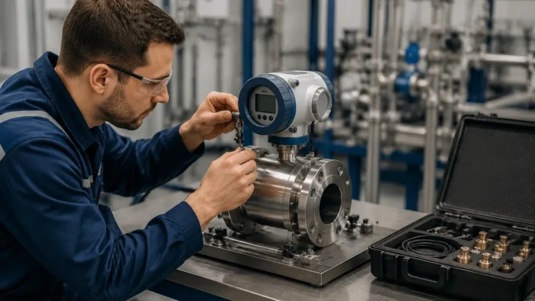
When dealing with highly corrosive, viscous, or extremely hot fluids, direct contact with the transmitter sensing element may be impossible. In these cases, diaphragm seals are used. A flexible membrane isolates the process fluid, and the pressure is transmitted to the sensor via a capillary tube filled with silicone oil or another fill fluid. While this protects the instrument, it introduces temperature-related drift, as the fill fluid expands or contracts with ambient temperature changes.
3. Impulse Line Maintenance
Impulse lines must be sloped correctly (typically 1:12 ratio) to prevent air pockets or sediment build-up. In cold climates, these lines may require heat tracing or insulation to prevent freezing or significant density shifts in the fluid within the lines.
Limitations and Challenges in the Process Environment
While the differenzdruckverfahren is a robust technology, it is not a "one-size-fits-all" solution. Engineers must account for the following limitations:
* Density Variation: Since the calculation relies on $\rho$ (density), any change in temperature that alters the liquid's density will result in a level error. If the process temperature fluctuates significantly, a temperature-compensated system or a different measurement technology may be required.
* Clogging and Coating: Fluids that crystallize, polymerize, or contain high solids can plug the impulse lines or the transmitter diaphragm. Regular flushing or the use of flush-mounted diaphragm seals can mitigate this.
* Mechanical Complexity: Compared to a top-mounted radar sensor, a DP system involves more potential leak points due to the valves, manifolds, and piping required for installation.
Frequently Asked Questions (FAQs)
Q: How does the differenzdruckverfahren handle foaming liquids?
A: One of the major advantages of DP measurement is that it is relatively unaffected by surface foam. Because it measures the mass of the liquid column (hydrostatic head), it ignores the light, non-dense foam on top, providing a reading of the actual liquid level.
Q: Can I use DP transmitters for interface measurement?
A: Yes. If you have two immiscible liquids with different densities (e.g., oil and water), the differenzdruckverfahren can be used to track the interface level, provided the total level remains above the top pressure tap.
Q: What is "Zero Elevation" and "Zero Suppression"?
A: These are calibration adjustments. Zero Suppression is used when the transmitter is mounted below the bottom of the tank, and the liquid in the impulse line creates a positive pressure at zero tank level. Zero Elevation is used in wet-leg applications where the reference leg pressure is higher than the high-pressure side at zero tank level.
Q: What units are typically used for DP level calibration?
A: While the output is usually 4-20mA or a digital fieldbus signal representing 0-100% level, the internal calibration is often performed in mmH2O, mbar, or kPa to match the specific hydrostatic head of the application.
For technical support in selecting the appropriate manifold or diaphragm seal configuration for your specific differenzdruckverfahren application, visiting the Main Page provides access to detailed engineering data and expert consultancy services. Ensuring the correct match between process chemistry and instrument material is the first step toward a maintenance-free installation.