Water Treatment Monitoring System
Water Treatment Monitoring System
In modern industrial and municipal infrastructure, a water treatment monitoring system serves as the central nervous system for ensuring water quality, process efficiency, and regulatory compliance. These systems integrate a variety of sensors and controllers to manage complex sequences, from raw water intake to the discharge of treated effluent. Among the various parameters tracked—such as pH, turbidity, and dissolved oxygen—level measurement remains one of the most critical variables for maintaining hydraulic balance and chemical dosing accuracy.
For engineers and plant operators, selecting the correct instrumentation is not merely a matter of measuring height; it involves understanding the chemical environment, physical constraints, and the specific demands of each treatment stage. This guide explores the technical foundations of level measurement within a water treatment monitoring system, providing a framework for technology selection and installation.
Measurement Principles in Water Treatment
Reliable monitoring begins with understanding how different sensors interact with the medium. In water treatment, four primary principles are commonly employed: ultrasonic, radar, hydrostatic, and magnetic.
Ultrasonic Level Measurement
Ultrasonic sensors operate on the Time-of-Flight (ToF) principle. The sensor emits an ultrasonic pulse that travels through the air, reflects off the liquid surface, and returns to the transducer. The distance is calculated based on the speed of sound. Since this is a non-contact method, it is ideal for general water storage and open channel flow measurement. However, it is sensitive to air temperature fluctuations and heavy foam.
Radar Level Measurement
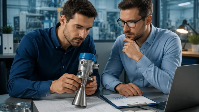
Similar to ultrasonic, radar uses ToF but employs high-frequency electromagnetic waves (typically 26GHz or 80GHz). Radar waves are unaffected by air temperature, pressure, or vacuum conditions. Radar is particularly effective in chemical storage tanks where vapors might interfere with ultrasonic signals. 80GHz radar, in particular, offers a narrow beam angle, which is useful for avoiding internal tank obstructions like agitators or ladders.
Hydrostatic Level Measurement
Hydrostatic transmitters measure the pressure exerted by the liquid column above the sensor. Based on the formula $P = \rho gh$ (where $P$ is pressure, $\rho$ is density, $g$ is gravity, and $h$ is height), the level is determined by the weight of the fluid. This is a contact-based method often used in deep wells, lift stations, and vented tanks. It is highly reliable but requires the liquid density to remain relatively constant for accurate readings.
Magnetic Level Gauges
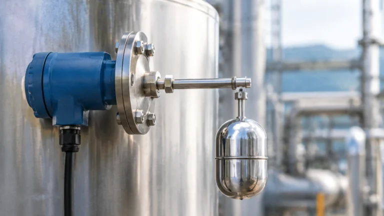
Magnetic level gauges utilize a float containing a permanent magnet that moves with the liquid level inside a bypass chamber. This magnet flips localized flags or interacts with a reed-chain transmitter to provide both visual and electronic feedback. These are preferred for high-pressure vessels or applications where a physical visual indicator is required for safety protocols.
Key Components of a Water Treatment Monitoring System
A comprehensive water treatment monitoring system is more than a collection of sensors; it is an integrated architecture. To explore specific hardware options for these systems, engineers often Review product options and application support to match instrument specifications with site requirements.
1. Primary Sensors: These include level, flow, pressure, and analytical sensors (pH, ORP, Conductivity).
2. Signal Transmitters: Convert raw sensor data into standardized industrial protocols such as 4-20mA, HART, Modbus RTU, or Profibus.
3. Local Controllers/PLCs: Process the incoming data to trigger alarms, start/stop pumps, or adjust chemical dosing valves.
4. Data Logging and HMI: Provide a graphical interface for operators to monitor real-time trends and historical data.
Technology Selection Table
The following table provides a general comparison of level measurement technologies used in various water treatment stages.
| Application Stage | Recommended Technology | Advantages | Limitations |
| :— | :— | :— | :— |
| Raw Water Intake | Ultrasonic / Hydrostatic | Cost-effective, handles large spans | Floating debris can affect ultrasonic accuracy |
| Chemical Dosing (Acids/Alums) | Radar (Non-contact) | Corrosion resistant, ignores vapors | Higher initial investment |
| Sedimentation / Clarifiers | Ultrasonic | Good for open surfaces | Surface foam can dampen signals |
| Sludge Holding Tanks | Radar / Hydrostatic | Penetrates steam/vapors | High solids content can foul hydrostatic diaphragms |
| Finished Water Reservoirs | Hydrostatic / Ultrasonic | High precision, easy installation | Requires venting for hydrostatic accuracy |
| Open Channel Flow | Ultrasonic | Standardized flow formulas | Requires precise mounting above flume/weir |
Installation Considerations for Accuracy
Even the most advanced sensor will fail to provide accurate data if installed incorrectly. Within a water treatment monitoring system, several physical factors must be addressed during the engineering phase.
Blocking Distance (Dead Zone)
All non-contact sensors (ultrasonic and radar) have a "blocking distance" or "dead zone" immediately below the sensor face. The liquid level cannot be measured accurately within this range. For example, if a sensor has a 0.3m (approx. 1ft) dead zone, the tank should be designed so the maximum fill level never reaches within 0.3m of the transducer.
Beam Angle and Obstructions
Non-contact sensors emit signals in a cone shape. Any internal structure—such as a pump support, a pipe, or an agitator—that enters this cone will create a false reflection. Engineers should select sensors with a narrow beam angle (e.g., 3° to 8°) for narrow tanks or use "False Echo Suppression" software to program the sensor to ignore fixed internal objects.
Stilling Wells and Bypass Chambers
In applications with heavy turbulence or surface foam (such as aeration tanks), installing the sensor inside a stilling well (a vertical pipe with vent holes) can stabilize the liquid surface. This provides a clean target for the signal and protects the sensor from mechanical stress.
Environmental Protection
Instruments in water treatment plants are often exposed to high humidity and corrosive gases (like H2S). Sensors should have an IP68 rating for submersible applications or at least IP66/67 for general outdoor use. Plastic housings (PVDF or PP) are preferred for chemical dosing areas to prevent corrosion.
Common Risks and Limitations
While modern water treatment monitoring systems are highly automated, they are not immune to environmental and process-related risks.
* Foam Interference: Heavy, dense foam can absorb ultrasonic pulses, leading to a "Loss of Echo" error. In these cases, high-frequency radar or hydrostatic pressure sensors are superior alternatives.
* Build-up and Scaling: In lime softening or wastewater applications, material can build up on the sensor face or diaphragm. Regular maintenance or the use of non-contact radar is necessary to prevent measurement drift.
* Temperature Gradients: Ultrasonic sensors rely on the speed of sound, which changes with air temperature. While most sensors include integrated temperature compensation, rapid shifts or solar heating of the sensor housing can still cause errors of 1-3%.
* Signal Interference: In large metal tanks, multiple reflections (multipath interference) can confuse a radar sensor. Proper positioning and the use of 80GHz technology, which has better focusing capabilities, mitigate this risk.
Information to Confirm Before Implementation
Before finalizing the design of a monitoring system, project stakeholders should confirm the following data points:
1. Media Characteristics: Is the liquid corrosive, abrasive, or prone to outgassing? What is the specific gravity?
2. Process Conditions: What are the maximum and minimum temperatures and pressures? Is there significant turbulence or foam?
3. Tank Geometry: What is the height and diameter? Are there internal obstructions?
4. Integration Requirements: Does the existing PLC support 4-20mA, or is a digital protocol like Modbus required for more granular diagnostics?
5. Maintenance Access: Is the sensor location accessible for calibration, or should a remote-display transmitter be used?
Frequently Asked Questions (FAQ)
Q: Can I use one type of sensor for the entire water treatment plant?
A: While it is tempting for spare parts standardization, it is rarely optimal. For example, a hydrostatic sensor is excellent for a deep well but unsuitable for a chemical tank where the liquid density changes frequently. A hybrid approach is usually most cost-effective.
Q: How often should level sensors in a water treatment monitoring system be calibrated?
A: For non-contact sensors in clean water, an annual check is often sufficient. For contact sensors in sludge or corrosive chemicals, quarterly inspections are recommended to check for diaphragm integrity or scaling.
Q: Is radar always better than ultrasonic?
A: Not necessarily. Ultrasonic remains a very cost-effective and reliable solution for simple water storage and open channel flow. Radar is generally reserved for more challenging environments (foam, vapor, vacuum) or where high precision (±1mm or ±2mm) is required.
Q: What is the impact of H2S gas on sensors?
A: Hydrogen sulfide (H2S) is common in wastewater treatment and is highly corrosive to copper and certain metals. Sensors used in these areas should have chemically resistant housings and cables, such as those made from Viton, PTFE, or high-grade stainless steel.
By carefully matching the measurement principle to the specific process stage, engineers can build a water treatment monitoring system that provides the reliable data necessary for safe and efficient operations. For detailed technical specifications and to explore the full range of industrial level instruments, professionals can Review product options and application support to ensure their system meets the rigorous demands of modern water management.