Vega Factor
Vega Factor
In the realm of industrial process control, the "Vega Factor" is often discussed by engineers as a benchmark for reliability and precision in radar level measurement. While the term is frequently associated with specific high-end hardware, in a broader technical sense, it represents the critical performance variables—frequency, signal-to-noise ratio, and beam focusing—that determine whether a level sensor will succeed or fail in a challenging environment.
For professionals managing water treatment, chemical processing, or oil and gas storage, understanding these factors is essential for selecting the right instrumentation. This guide explores the technical principles of modern radar level measurement, the impact of high-frequency technology, and the practical considerations for implementing these solutions in industrial settings.
Principles of Radar Level Measurement
To understand the factors that contribute to measurement accuracy, one must first understand the underlying physics of radar technology. Industrial radar level meters primarily operate on two principles: Pulse Radar and Frequency Modulated Continuous Wave (FMCW) Radar.
Pulse Radar
Pulse radar sensors emit short microwave pulses toward the medium. The sensor measures the time it takes for the pulse to travel to the surface and back to the antenna. This "Time-of-Flight" (ToF) is directly proportional to the distance. While effective for simple applications, pulse radar often struggles with low-dielectric materials or environments with significant surface turbulence.
FMCW Radar
FMCW radar is the technology behind the most advanced level meters. Instead of sending pulses, the sensor emits a continuous signal with a constantly changing frequency. The reflection from the product surface is received, and the frequency difference between the emitted and received signal is calculated. This difference is proportional to the distance. FMCW provides a much higher signal-to-noise ratio and better resolution, which is a core component of what engineers refer to as the "Vega Factor" in high-precision measurement.
The Role of Dielectric Constants
The dielectric constant (εr) of a material determines how much of the radar signal is reflected. Water has a high dielectric constant (~80), making it an excellent reflector. In contrast, hydrocarbons and certain solids have low dielectric constants (<2), meaning most of the signal passes through the material rather than reflecting. High-performance radar units must have sufficient sensitivity to detect these weak echoes, a capability that defines the quality of the instrument.
Understanding Signal Sensitivity and the "Vega Factor"
When evaluating radar sensors, the "Vega Factor" effectively refers to the instrument's ability to distinguish the true level echo from background noise and false reflections. This is achieved through three primary technical domains: frequency, beam angle, and signal processing algorithms.
Frequency and Beam Angle
The frequency of a radar sensor (measured in GHz) dictates the beam angle. A higher frequency allows for a narrower beam with a smaller antenna. For example, a traditional 26GHz radar might have a beam angle of 10° to 20°, whereas an 80GHz radar can achieve a beam angle as narrow as 3°.
A narrow beam is critical in narrow tanks or vessels with internal obstructions like agitators, heating coils, or ladders. By focusing the energy into a tight beam, the sensor avoids these obstacles, reducing the risk of false echoes. This focusing ability is a primary driver in the shift toward 80GHz technology in the Main Page of industrial automation.
Signal-to-Noise Ratio (SNR)
In complex environments—such as those with heavy steam, dust, or foam—the signal-to-noise ratio becomes the deciding factor. Advanced sensors use sophisticated Fast Fourier Transform (FFT) processing to filter out noise. The "factor" of success here is the software's ability to track the "peak" of the level signal even when it is partially obscured by environmental interference.
Technical Comparison: 26GHz vs. 80GHz Radar
Choosing between different radar frequencies is a balance of cost, application requirements, and physical constraints. The following table outlines the key differences that influence the selection process.
| Feature | 26GHz Radar | 80GHz Radar |
| :— | :— | :— |
| Beam Angle | Wide (approx. 10° – 20°) | Narrow (approx. 3° – 6°) |
| Antenna Size | Larger (typically DN50 – DN150) | Compact (as small as DN25) |
| Measurement Accuracy | ±2 mm to ±5 mm | ±1 mm |
| Obstruction Tolerance | Moderate (requires clear path) | High (can bypass internal structures) |
| Surface Turbulence | Good performance | Excellent performance |
| Dust/Steam Penetration | Strong | Very Strong (due to high energy density) |
| Typical Applications | Large storage tanks, water basins | Small process vessels, corrosive chemicals, solids |
Installation Considerations for High-Precision Level Meters
Even the most advanced sensor will fail if the installation does not account for the physics of microwave propagation. To maximize the "Vega Factor" of reliability, engineers should follow these guidelines:
1. Nozzle Height and Diameter: The antenna should ideally extend slightly beyond the mounting nozzle to prevent internal reflections. If using a high-frequency 80GHz sensor, the narrow beam allows for longer and narrower nozzles than traditional 26GHz units.
2. Mounting Position: Sensors should never be mounted in the center of a tank (to avoid multiple reflections from the tank walls) or too close to the wall (to avoid signal interference). A position at 1/3 of the tank radius is generally recommended.
3. Inflow Interference: Ensure the radar beam does not intersect the path of the falling product during filling. This creates significant noise and can lead to temporary loss of signal.
4. Agitators and Obstructions: If an agitator is present, the sensor should be positioned such that the beam is perpendicular to the blades or uses software mapping to "mask" the agitator as a static obstruction.

Application-Specific Selection Criteria
Different industries face unique challenges that dictate which measurement factors are most important.
Water and Wastewater Treatment
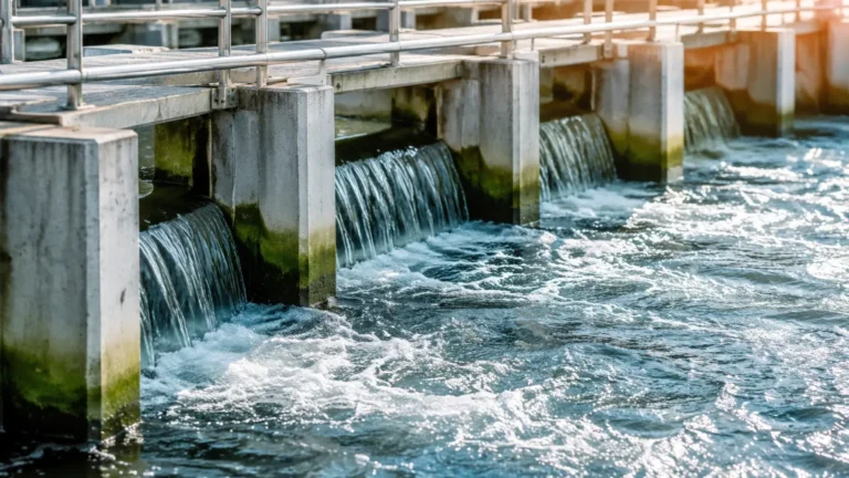
In water treatment, sensors are often exposed to the elements. Here, the factor of success is weather resistance and the ability to ignore condensation on the antenna. Ultrasonic sensors are common, but radar is increasingly preferred for its immunity to air temperature fluctuations and wind.
Chemical and Petrochemical
In these environments, the dielectric constant of the medium is often low, and the atmosphere may be explosive. Sensors must be ATEX/IECEx certified and possess high sensitivity to track low-dk liquids like hexane or benzene. The use of PTFE or PEEK antenna covers is mandatory to prevent corrosion.
Solids and Powders
Measuring the level of solids (like grain, cement, or plastic pellets) involves uneven surfaces and heavy dust. High-frequency radar is superior here because the narrow beam can be aimed at specific points on the material cone, and the high frequency penetrates dust clouds more effectively than lower frequencies.
Limitations and Troubleshooting
While radar is one of the most versatile level measurement technologies, it is not without limitations. Understanding these boundaries is part of the "Vega Factor" in engineering design.
* Heavy Foam: Extremely dense, thick foam can absorb the radar signal entirely. In such cases, a guided wave radar (GWR) or a hydrostatic pressure transmitter may be a more reliable choice.
* Extremely Low Dielectric Constants: If a material has a dielectric constant below 1.4, standard non-contact radar may struggle. A GWR, which uses a physical probe to guide the signal, is often the solution.
* Vacuum and High Pressure: While radar works in a vacuum (unlike ultrasonic sensors), extreme pressures can affect the mechanical integrity of the antenna seal. Always verify the pressure rating of the process connection.
Frequently Asked Questions (FAQ)
Q: Does the frequency of the radar affect its ability to measure through foam?
A: Generally, lower frequencies (e.g., 6GHz or 10GHz) penetrate foam better than higher frequencies. However, higher frequencies (80GHz) provide better signal reflection from the liquid surface *underneath* light foam due to their higher energy density. For heavy, thick foam, non-contact radar is often not recommended.
Q: Can I use an 80GHz radar in a tank with a plastic liner?
A: Yes. One of the advantages of high-frequency radar is that it can often measure through plastic tank tops or liners, provided the material is not conductive and the thickness is consistent.
Q: How does condensation affect the measurement?
A: Modern radar sensors, particularly those with encapsulated antennas or convex lenses, are designed to allow droplets to run off. While heavy condensation can attenuate the signal, it rarely causes a total loss of measurement in high-quality FMCW systems.
Q: What is the "dead zone" or "blocking distance"?
A: This is the area immediately below the antenna where the sensor cannot make an accurate measurement. For many modern high-frequency sensors, this zone is very small (often less than 50 mm or 2 inches), allowing for full utilization of the tank capacity.
Conclusion
Achieving reliable level measurement is not about buying the most expensive sensor, but about understanding the technical factors—the "Vega Factor"—that align a sensor's capabilities with the application's demands. By prioritizing high signal sensitivity, narrow beam angles, and robust signal processing, facilities can reduce maintenance costs and improve process safety.
For those seeking to implement these technologies, it is vital to consult with manufacturers who offer a range of solutions, from radar to ultrasonic and hydrostatic systems. You can Review product options and application support to find the specific configuration that meets your industrial requirements, ensuring that your level measurement remains accurate regardless of the environmental challenges.