Differenzdruckmethode
Differenzdruckmethode
In the field of industrial process control, the measurement of liquid levels within tanks and vessels is a fundamental requirement. Among the various technologies available, the differenzdruckmethode (differential pressure method) remains one of the most widely applied techniques due to its versatility, reliability, and cost-effectiveness. This method utilizes the principle of hydrostatic pressure to determine the height of a liquid column, providing a robust solution for both open and pressurized containers.
Understanding the engineering principles, installation nuances, and technical limitations of the differenzdruckmethode is essential for instrumentation engineers and plant operators. This guide provides a comprehensive technical overview of the technology, its application in modern industry, and the criteria for selecting the appropriate measurement hardware.
Measurement Principle of the Differenzdruckmethode
The differenzdruckmethode is based on Pascal’s Law, which states that the pressure exerted by a static liquid at a specific depth is directly proportional to the height of the liquid column above that point, the density of the liquid, and the force of gravity. The mathematical relationship is expressed as:
P = ρ × g × h
Where:
* P is the hydrostatic pressure (measured in Pascals or bar).
* ρ (rho) is the density of the fluid (kg/m³).
* g is the acceleration due to gravity (approximately 9.81 m/s²).
* h is the height of the liquid column (meters).
In a level measurement application, the differential pressure transmitter measures the difference between two pressure points. By knowing the density of the medium and the gravitational constant, the transmitter or the control system can calculate the level (h) based on the measured pressure (P).
Open vs. Closed Vessel Configurations
The application of the differenzdruckmethode differs depending on whether the vessel is vented to the atmosphere or pressurized.
1. Open Vessels: In an open or vented tank, the high-pressure side of the transmitter is connected to the bottom of the vessel. The low-pressure side is vented to the atmosphere. Since the atmospheric pressure acts equally on the liquid surface and the low-pressure side of the sensor, it cancels out, leaving only the hydrostatic pressure of the liquid column to be measured.
2. Closed/Pressurized Vessels: In closed systems, such as boilers or chemical reactors, the headspace above the liquid is often pressurized with gas or steam. To accurately measure the level, the pressure in the headspace must be subtracted from the total pressure at the bottom. The high-pressure side of the transmitter is connected to the bottom of the tank, while the low-pressure side is connected to the top (the gas phase). The resulting differential pressure represents solely the weight of the liquid column.
System Components and Hardware
A standard setup using the differenzdruckmethode typically involves several key components. Selecting the right hardware depends on the chemical properties of the fluid, temperature ranges, and the physical layout of the plant.
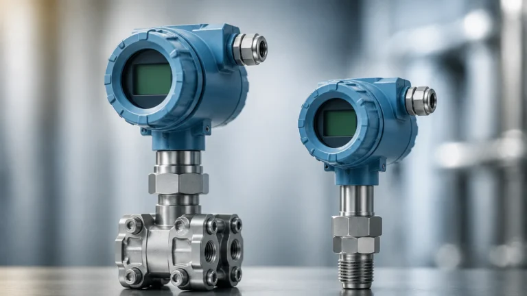
Differential Pressure Transmitters
Modern transmitters, such as those provided by Welk, utilize high-precision silicon or ceramic sensors. These devices convert the mechanical displacement of a diaphragm into an electrical signal (typically 4-20 mA or a digital fieldbus protocol like HART or Profibus). For a broad range of industrial solutions, engineers can Review product options and application support to find transmitters compatible with specific chemical environments.
Impulse Lines and Manifolds
Impulse lines are the small-bore pipes that connect the process vessel to the transmitter. In many applications, a three-valve or five-valve manifold is installed between the vessel and the transmitter. This allows for the isolation of the instrument for maintenance, zero-point calibration, and bleeding of trapped air or condensate without shutting down the process.
Diaphragm Seals and Capillaries
In applications involving corrosive, highly viscous, or hygienic fluids, the process medium must not come into direct contact with the transmitter’s internal sensors. In these cases, diaphragm seals are used. A flexible diaphragm separates the process fluid from a fill fluid (usually silicone oil), which transmits the pressure through capillary tubes to the sensor. While effective, capillaries introduce temperature sensitivity, as the fill fluid expands or contracts with ambient temperature changes.
Selection Criteria for Industrial Applications
Choosing the differenzdruckmethode over other technologies like radar or ultrasonic sensors requires a detailed evaluation of the process conditions. The following table outlines the primary selection criteria for DP-based level measurement.
| Criteria | Consideration for Differenzdruckmethode |
| :— | :— |
| Fluid Density | Must be constant or compensated. Changes in density directly affect accuracy. |
| Vessel Type | Suitable for both open and high-pressure closed tanks. |
| Media State | Best for clean liquids. Slurries or solids require diaphragm seals to prevent clogging. |
| Temperature | High temperatures require cooling elements or remote diaphragm seals. |
| Accuracy | High (typically 0.075% to 0.1% of span), provided density is stable. |
| Cost | Generally lower than non-contact radar for standard pressurized applications. |
Installation Considerations and Best Practices
The accuracy of the differenzdruckmethode is heavily dependent on correct installation. Failure to account for physical layout can lead to significant measurement errors.
The "Wet Leg" vs. "Dry Leg" Setup
In closed vessels where the gas in the headspace might condense (e.g., steam), the low-pressure impulse line can fill with liquid. This is handled in two ways:
* Dry Leg: Used when the gas is non-condensable. The low-pressure line remains filled with gas. The transmitter is calibrated with the assumption that the low-pressure side is empty.
* Wet Leg: Used when the gas is likely to condense. The low-pressure line is intentionally filled with a reference liquid (often the process fluid or water). The weight of this liquid column must be mathematically "zeroed out" during the transmitter configuration (a process known as zero suppression).
Mounting Position
The transmitter should ideally be mounted below the lower tapping point of the vessel. This ensures that the impulse lines remain full of liquid and reduces the risk of gas bubbles becoming trapped in the lines, which would cause erratic readings. If the transmitter must be mounted above the tapping point, special precautions (such as siphons or specific software compensation) are required.
Zero-Point Calibration
Once installed, the system must be calibrated for the specific installation height. If the transmitter is located 1 meter below the bottom of the tank, it will sense 1 meter of head pressure even when the tank is empty. This is corrected through "Zero Elevation" or "Zero Suppression" settings within the transmitter's electronics.

Limitations and Potential Risks
While the differenzdruckmethode is a workhorse of the industry, it is not without its limitations. Engineers should be aware of the following risks:
1. Density Fluctuations: Since the method measures weight (pressure), any change in fluid density—caused by temperature swings or changes in chemical composition—will be interpreted as a change in level. In applications with variable density, a second pressure sensor or a temperature-based compensation algorithm is necessary.
2. Impulse Line Clogging: In applications with suspended solids or fluids that crystallize, impulse lines can become blocked. This leads to a "frozen" reading or slow response times. Regular flushing or the use of flush-mounted diaphragm seals is recommended for these environments.
3. Ambient Temperature Effects: For systems using capillaries and diaphragm seals, large fluctuations in ambient temperature can cause the fill fluid to expand, creating a false pressure reading. This is often mitigated by using "balanced" capillary lengths or electronic differential pressure (eDP) systems.
4. Gas Entrapment: In liquid-filled impulse lines, small bubbles of gas can significantly alter the pressure reading. Proper sloping of impulse lines (typically 1:12 slope) and the use of vent valves are critical to maintaining accuracy.
Comparison with Alternative Technologies
To provide a balanced engineering perspective, it is useful to compare the differenzdruckmethode with other common technologies found on the Main Page of industrial instrumentation providers.
* Radar (GWR or Non-Contact): Radar is independent of density changes and is excellent for foaming or turbulent surfaces. However, DP is often more cost-effective for high-pressure vessels where the density of the liquid is well-known.
* Ultrasonic: Ultrasonic sensors are non-contact and easy to install but cannot be used in vacuum or high-pressure environments, whereas DP transmitters thrive in those conditions.
* Hydrostatic (Submersible): These are essentially DP sensors used in open tanks or wells. They are simpler to install but cannot handle the headspace pressure of a closed vessel.
Frequently Asked Questions (FAQ)
Q: Can the differenzdruckmethode be used for interface measurement?
A: Yes. If two immiscible liquids with different densities are in the same tank (e.g., oil and water), a DP transmitter can measure the height of the interface, provided the total level remains above the top tapping point.
Q: What is Electronic Differential Pressure (eDP)?
A: eDP uses two separate pressure sensors connected by an electrical cable instead of impulse lines or capillaries. This eliminates issues related to temperature effects on fill fluids and the maintenance of wet/dry legs.
Q: How often should a DP level transmitter be calibrated?
A: This depends on the criticality of the process and the stability of the environment. Most modern digital transmitters maintain their accuracy for 2 to 5 years, but annual zero-checks are standard practice in many regulated industries.
Q: Does the shape of the tank affect the measurement?
A: The pressure at the bottom of the tank is only dependent on the height and density, not the shape or volume of the tank. However, if the goal is to measure volume (liters or gallons) rather than level, the control system must use a strapping table to account for the tank's geometry.
Summary for Engineering Selection
The differenzdruckmethode remains a primary choice for level measurement in the chemical, oil and gas, and water treatment industries. Its ability to handle high pressures and temperatures, combined with the precision of modern electronics, makes it a highly reliable tool. When selecting a system, engineers must prioritize density stability and ensure that the installation (wet leg, dry leg, or diaphragm seal) is compatible with the physical properties of the process medium.
For those seeking specific hardware specifications or customized OEM/ODM services for level measurement, visiting the Main Page of a professional manufacturer like Welk provides access to technical data sheets and application-specific guidance. By adhering to rigorous installation standards and understanding the underlying physics of hydrostatic pressure, the differenzdruckmethode provides a long-term, low-maintenance solution for complex industrial level sensing needs.