Dielectric Constant Water
Dielectric Constant Water
In the field of industrial process control, the dielectric constant of a medium is one of the most critical physical properties influencing the selection and performance of level measurement instrumentation. When discussing dielectric constant water, we are addressing a substance with a relatively high permittivity compared to most industrial oils and gases. This high value makes water an ideal candidate for certain measurement technologies, such as radar and capacitance, but it also necessitates a deep understanding of how environmental factors like temperature and purity can shift these values and affect instrument accuracy.
Understanding Dielectric Constant in Industrial Contexts
The dielectric constant, often denoted by the Greek letter epsilon ($ε_r$) and also referred to as relative permittivity, is a dimensionless measure of a material's ability to store electrical energy in an electric field. It is defined relative to a vacuum, which has a dielectric constant of 1.0.
In level measurement, the dielectric constant determines how much energy from an electromagnetic wave will be reflected at the surface of a liquid. For technologies like Guided Wave Radar (GWR) or Non-contact Radar, the strength of the return signal (the echo) is directly proportional to the difference between the dielectric constant of the upper medium (usually air or vapor) and the lower medium (the liquid).
The Physics of Dielectric Constant Water
Pure water at room temperature (approximately 20°C to 25°C) has a dielectric constant of roughly 80. This is exceptionally high when compared to materials like hexane ($ε_r ≈ 1.9$), diesel ($ε_r ≈ 2.1$), or even some alcohols. The high dielectric constant water exhibits is due to the polar nature of the water molecule ($H_2O$). The oxygen atom attracts electrons more strongly than the hydrogen atoms, creating a dipole moment. In an external electric field, these molecules align themselves, effectively opposing the field and storing significant energy.
Temperature Sensitivity
One of the most important factual boundaries for engineers to recognize is that the dielectric constant of water is not a fixed constant; it is highly temperature-dependent. As temperature increases, the thermal agitation of the molecules increases, making it harder for them to align with an electric field. Consequently, the dielectric constant decreases as temperature rises.
* At 0°C: $ε_r ≈ 88$
* At 20°C: $ε_r ≈ 80$
* At 100°C: $ε_r ≈ 55$
* At 200°C: $ε_r ≈ 35$
In high-pressure boiler applications where temperatures may exceed 300°C, the dielectric constant can drop below 20. While still high enough for reliable radar detection, this shift must be accounted for in capacitance-based systems that rely on a stable dielectric value for calibration.
Impact on Radar Level Measurement
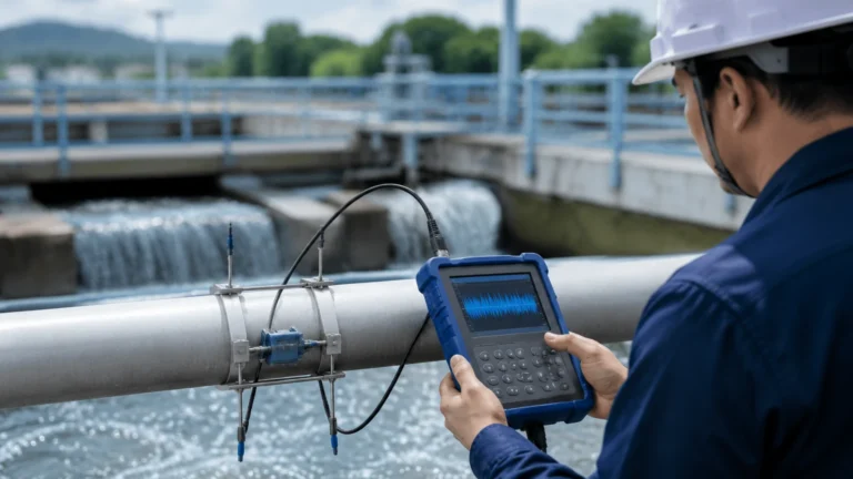
Radar level meters operate on the Time of Flight (ToF) principle. A microwave signal is emitted, travels through the headspace, hits the liquid surface, and reflects back to the sensor. The reflection coefficient ($R$) is calculated based on the change in dielectric constant:
$$R = \frac{\sqrt{ε_{r2}} – \sqrt{ε_{r1}}}{\sqrt{ε_{r2}} + \sqrt{ε_{r1}}}$$
Where $ε_{r1}$ is the dielectric constant of the air/vapor space and $ε_{r2}$ is the dielectric constant of the liquid.
Because the dielectric constant water is so high ($ε_r ≈ 80$), the reflection is very strong. Approximately 80% of the microwave energy is reflected back to the sensor when hitting a water surface. This makes water one of the easiest liquids to measure with radar, even in the presence of surface turbulence or slight foam, as the signal-to-noise ratio remains high.
However, in applications involving high-pressure steam, the dielectric constant of the steam (the headspace) increases above 1.0. This slows down the microwave signal, leading to a "propagation delay" that can cause the sensor to report a level lower than the actual level. Advanced radar systems, such as those found on the Welk Main Page, often include compensation algorithms or reference probes to correct for this vapor phase effect.
Impact on Capacitance Level Measurement
Capacitance level sensors treat the tank, the probe, and the process medium as a giant capacitor. The capacitance ($C$) is defined by the formula:
$$C = ε_0 ε_r \frac{A}{d}$$
Where $A$ is the area of the electrodes and $d$ is the distance between them. Since water has a high $ε_r$, even a small change in water level results in a significant and measurable change in capacitance.
For water-based applications, insulated probes are typically required because water is conductive. If the water contains dissolved minerals or salts (increasing conductivity), the capacitance sensor essentially measures the capacitance of the insulation on the probe. The high dielectric constant water ensures that the system remains sensitive, but users must ensure the medium remains relatively homogenous to avoid calibration drift.
Technology Selection Table for Water Applications
When selecting a level meter based on the dielectric properties and process conditions of water, the following table serves as a general engineering guide:
| Technology | Suitability for Water | Min. Dielectric Constant (ε_r) | Key Advantage | Limitation |
| :— | :— | :— | :— | :— |
| Non-contact Radar | Excellent | > 1.4 | No contact with media; low maintenance. | Can be affected by heavy foam or internal tank obstructions. |
| Guided Wave Radar | Excellent | > 1.2 | Highest signal stability; ignores foam/turbulence. | Contacting; probe can accumulate scale or debris. |
| Ultrasonic | Good | N/A (Mechanical) | Cost-effective for open channels/sumps. | Affected by temperature gradients and wind. |
| Capacitance | Good | > 2.0 | High pressure/temperature capability. | Requires recalibration if the liquid composition changes significantly. |
| Hydrostatic | Good | N/A (Pressure) | Simple installation; independent of dielectric. | Affected by changes in liquid density. |
Installation and Engineering Best Practices
To ensure accurate measurement regardless of the dielectric constant water fluctuations, several installation factors must be considered:
1. Nozzle Geometry: For non-contact radar, the nozzle height and diameter should be optimized to prevent "ringing" or false reflections from the nozzle edge. Since water provides a strong reflection, the sensor gain can often be turned down, which helps ignore minor internal tank reflections.
2. Stilling Wells: In applications with extreme turbulence or heavy foam, a stilling well (for non-contact radar) or a coaxial probe (for GWR) provides a calm surface and concentrates the signal energy. This is particularly useful in wastewater treatment where the dielectric constant might vary slightly due to suspended solids.
3. Vapor Compensation: In high-temperature water applications (e.g., boiler drums), the dielectric constant of the steam becomes a factor. Use GWR with a dynamic vapor compensation (DVC) probe to maintain accuracy within ±5 mm even as the steam density changes.
4. Grounding: For capacitance and GWR sensors, ensure the instrument is properly grounded to the metal tank wall. In plastic tanks, a ground rod or reference electrode must be installed to complete the circuit.
Limitations and Challenges
While the high dielectric constant water makes it generally easy to measure, there are specific scenarios that present challenges:
* Heavy Foam: While water reflects radar well, thick, dense foam can absorb the signal or create a false reflection. If the foam is conductive (common in chemical water treatment), GWR is the preferred technology as it can "cut through" the foam to find the liquid interface.
* Condensation: In water tanks, condensation often forms on the sensor face. While the high dielectric of the water surface usually overcomes the signal loss from droplets, excessive buildup on a radar antenna can cause a "near-zone" blockage. Using PTFE-faced antennas or air purging can mitigate this.
* Coating and Scaling: In hard water applications, calcium carbonate or other minerals can build up on contacting probes. This scale has a different dielectric constant than water (typically $ε_r ≈ 6$ to $9$), which can lead to measurement errors in capacitance-based systems.
Frequently Asked Questions
Q: Does the salinity of water change its dielectric constant?
A: Yes, but the effect on radar measurement is minimal. While salinity increases conductivity, radar signals reflect off the dielectric interface. High conductivity actually improves the reflection. For capacitance sensors, however, increased salinity makes the water more conductive, requiring the use of an insulated probe.
Q: Can I use a radar sensor designed for oil on a water tank?
A: Generally, yes. Sensors designed for low-dielectric media (like oils) are highly sensitive. Since the dielectric constant water is much higher, the sensor will receive a very strong signal. You may simply need to adjust the sensitivity or gain settings to prevent signal saturation.
Q: How does the dielectric constant of ice compare to water?
A: This is a critical distinction. While liquid water has a dielectric constant of ~80, ice has a dielectric constant of approximately 3.2. This drastic drop occurs because the water molecules are locked in a crystal lattice and cannot rotate to align with the electric field. This is why radar can often see through ice layers to the water underneath, or why a sensor might fail to detect a level if it is only calibrated for liquid water and the tank freezes.
Conclusion
Understanding the dielectric constant water is foundational for any engineer tasked with selecting level measurement instrumentation. The high permittivity of water ensures robust signal reflections for radar and significant capacitance changes for probe-based sensors. However, the sensitivity of this value to temperature and the physical state of the water (liquid vs. ice vs. vapor) requires careful application engineering.
For professionals seeking reliable hardware that accounts for these physical variables, exploring the technical specifications of radar and ultrasonic systems is the next logical step. By matching the technology to the specific dielectric behavior of the process media, plants can achieve higher accuracy, reduced maintenance, and improved safety. For a comprehensive overview of available technologies and customized solutions, please visit the Main Page to review product options and application support.