Stilling Wells
Stilling Wells
In the field of industrial level measurement, achieving a stable and accurate reading is often complicated by the physical dynamics of the process media. Turbulence, surface agitation, foam, and internal tank obstructions can all degrade the signal quality of level sensors. Stilling wells, also known as bypass pipes or surge pipes, are essential mechanical components designed to mitigate these issues. By creating a protected, calm environment for the sensor, stilling wells allow for high-precision measurement even in the most demanding industrial environments.
Measurement Principles and Functions
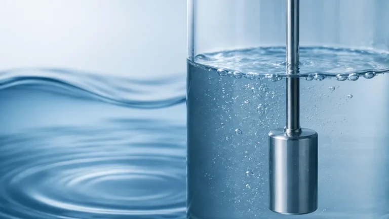
A stilling well is essentially a vertical pipe installed within a vessel or mounted externally as a bypass chamber. It operates on the principle of communicating vessels, ensuring that the liquid level inside the pipe is identical to the level in the main tank, while isolating the sensor from external disturbances.
1. Turbulence Damping
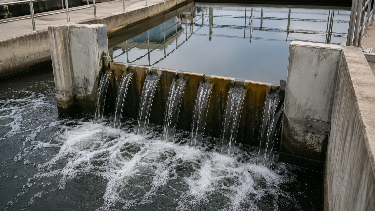
In tanks equipped with high-speed agitators or top-entry filling pipes, the liquid surface is frequently characterized by waves and vortices. These fluctuations cause "noise" in ultrasonic and radar signals. The stilling well acts as a mechanical filter; while the liquid level can equalize through small holes or the bottom opening, the high-frequency surface waves are suppressed by the pipe walls.
2. Foam Suppression
Chemical and wastewater applications often involve liquids that generate thick layers of foam. Most non-contact level sensors, such as ultrasonic transmitters, struggle to distinguish between the foam surface and the actual liquid level. A stilling well allows the sensor to bypass the foam layer, as the foam typically remains on the exterior of the pipe while the clear liquid enters the well from below.
3. Signal Amplification for Radar
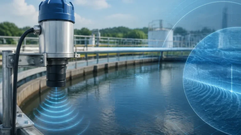
For non-contact radar level meters, a stilling well serves a dual purpose. Beyond damping turbulence, it acts as a waveguide. By confining the electromagnetic waves within the metallic pipe, the signal energy is concentrated rather than being dispersed across the tank. This is particularly beneficial for liquids with low dielectric constants, where signal reflection is naturally weak.
4. Elimination of Internal Obstructions
Many industrial tanks contain heating coils, ladders, or support struts. These objects can create false echoes (parasitic reflections) for radar and ultrasonic sensors. A stilling well provides a clear, unobstructed path for the measurement signal, ensuring that the sensor only "sees" the liquid surface.
Technical Selection Criteria
Selecting the correct stilling well requires an understanding of both the sensor technology and the chemical properties of the media. The following table provides a general guideline for matching stilling well specifications with common measurement technologies.
| Feature | Radar Level Meter | Ultrasonic Sensor | Hydrostatic Probe |
| :— | :— | :— | :— |
| Recommended Diameter | 50 mm to 200 mm | 100 mm to 300 mm | 50 mm to 100 mm |
| Material | Stainless Steel (316L) or Plastic | PVC, PP, or Stainless Steel | PVC or Stainless Steel |
| Vent Holes | Mandatory (Top) | Mandatory (Top) | Optional |
| Internal Surface | Smooth, seamless finish | Smooth finish | Standard finish |
| Perforations | Small (3-6 mm) along length | Larger holes or bottom entry | Bottom entry only |
| End Cap | Usually open or 45° cut | Open bottom | Open or weighted |
Material Compatibility
The choice of material is dictated by the corrosivity of the fluid and the operating temperature. Stainless steel 316L is the standard for oil, gas, and high-temperature chemical applications. For water treatment or aggressive acids at lower temperatures, PVC, Polypropylene (PP), or PTFE-lined pipes are preferred to prevent corrosion and scaling.
Pipe Diameter and Beam Angle
The diameter of the stilling well must be larger than the sensor’s signal spread. For ultrasonic sensors, which have a wider beam angle (typically 5° to 12°), a wider pipe is necessary to prevent the signal from hitting the pipe walls prematurely. Radar sensors can operate in narrower pipes, but the internal diameter must be consistent throughout the length of the well to avoid impedance changes that cause false reflections.
Installation Considerations and Best Practices
The effectiveness of a stilling well is highly dependent on the quality of its installation. Poorly installed wells can lead to measurement lag or mechanical failure.
Vertical Alignment (Plumbness)
A stilling well must be installed perfectly vertical. Even a slight tilt can cause a float to stick or a radar signal to reflect off the side of the pipe rather than the liquid surface. For every 10 meters of height, the deviation should not exceed 10 mm to 20 mm, depending on the sensor type.
Venting and Pressure Equalization
For the liquid level inside the well to match the level in the tank, the air pressure must be equalized. A vent hole must be drilled near the top of the stilling well, above the maximum possible liquid level. Without this hole, an air pocket can form, pushing the liquid level down and causing significant measurement errors.
Hole Placement and Sizing
To allow liquid to enter the well, holes or slots are typically drilled along the length of the pipe.
- Size: Holes are usually 3 mm to 12 mm in diameter. Smaller holes provide better damping but are more prone to clogging.
- Deburring: It is critical that the inside of the pipe is deburred after drilling. Any metal shards or rough edges left inside the pipe will create false echoes for radar sensors or catch on mechanical floats.
Bottom Clearance
The bottom of the stilling well should generally terminate 50 mm to 100 mm above the tank floor. This prevents the accumulation of sludge or sediment from blocking the entry of the liquid. In cases where the well must reach the bottom for structural stability, large side-entry slots should be cut at the base.
Limitations and Common Risks
While stilling wells solve many measurement problems, they are not a universal solution and introduce their own set of challenges.
* Build-up and Clogging: In applications involving heavy oils, waxes, or wastewater with high solids content, material can accumulate on the inner walls of the well. This build-up can trap floats or narrow the effective diameter for radar signals. Regular cleaning or the use of specialized coatings may be required.
* Response Time Lag: If the entry holes are too small or too few, the liquid level inside the well may lag behind the actual level in the tank during rapid filling or emptying cycles. This is a critical safety consideration for high-level alarm systems.
* Specific Gravity Changes: For displacement-based level measurement, changes in the liquid's specific gravity will affect the float's buoyancy. While the stilling well protects the float, it does not compensate for density fluctuations.
* Stagnant Zones: In the food and beverage industry, stilling wells are often discouraged because they create "dead zones" where product can stagnate and bacteria can grow. Hygienic applications typically require bypass chambers that can be fully cleaned via CIP (Clean-In-Place) systems.
Practical Engineering FAQs
Q: Can I use a plastic stilling well with a radar level meter?
A: Yes, but with caveats. A metallic pipe acts as a waveguide, which improves signal strength. A plastic pipe does not have the same waveguide effect. If using plastic, the radar treats it more like an open-tank application, and you must ensure the pipe diameter is large enough to accommodate the full beam width without interference.
Q: How do I prevent the "antenna effect" in tall stilling wells?
A: For very long stilling wells, ensuring the pipe sections are joined with precision-aligned flanges or internal sleeves is vital. Any gap or misalignment at a joint will create a massive reflection point that can be mistaken for the liquid level.
Q: Are stilling wells necessary for Guided Wave Radar (GWR)?
A: Generally, no. GWR uses a physical probe (cable or rod) to guide the signal, which already provides the benefits of a stilling well (turbulence resistance and signal focus). However, a stilling well may still be used with GWR to provide mechanical protection for the probe in high-flow environments.
Maintenance and Maintenance Guidance
Routine maintenance of stilling wells is often overlooked until a measurement failure occurs. In many industrial processes, a bi-annual inspection is recommended. This involves:
1. Visual Inspection: Checking for corrosion at the liquid-air interface.
2. Cleaning: Using a high-pressure water jet or mechanical brush to remove scaling and biological growth.
3. Vent Verification: Ensuring the top vent hole is not obstructed by dust or crystallized process media.
For engineers and plant managers looking to optimize their level measurement strategy, selecting the right combination of sensor and mounting hardware is critical. You can Review product options and application support on our Main Page to find the specific radar, ultrasonic, or hydrostatic solutions that pair best with your existing or planned stilling well installations.
Conclusion
Stilling wells remain a cornerstone of reliable level measurement in heavy industry. By understanding the physics of wave damping and signal propagation within these pipes, engineers can significantly improve the accuracy and longevity of their instrumentation. Whether managing a chemical reactor with intense agitation or a water reservoir prone to surface wind, a properly designed stilling well ensures that the level meter provides the precise data required for safe and efficient operations.