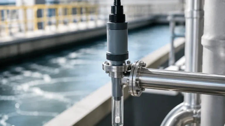
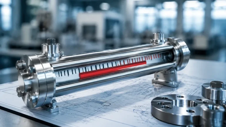
Flow Sensor Ultrasonic
Flow Sensor Ultrasonic
In the landscape of industrial automation and process control, the ability to measure fluid movement accurately without interrupting the flow or compromising the integrity of the piping system is a significant advantage. The flow sensor ultrasonic has emerged as a premier solution for these requirements. Utilizing high-frequency sound waves to determine the velocity of a liquid, these sensors provide a non-intrusive, reliable, and highly accurate method for monitoring everything from potable water to aggressive chemical reagents.
As industries move toward smarter, more data-driven operations, understanding the nuances of ultrasonic flow measurement becomes essential for plant engineers and system integrators. This guide explores the fundamental principles, selection criteria, and practical installation considerations for ultrasonic flow technology.
Understanding the Measurement Principles
Ultrasonic flow measurement is primarily based on two distinct physical phenomena: Transit-time and the Doppler Effect. Choosing the right principle depends entirely on the characteristics of the fluid being measured.
Transit-Time Method
Transit-time ultrasonic flow meters utilize a pair of transducers that act as both transmitters and receivers. They are mounted on opposite sides of a pipe (or at a specific distance apart on the same side). The sensor sends a pulse of ultrasonic energy from Transducer A to Transducer B, and then from B to A.
When the fluid is stationary, the time taken for the pulse to travel in both directions is identical. However, when the fluid is moving, the pulse traveling with the flow (downstream) moves faster than the pulse traveling against the flow (upstream). The flow velocity ($V$) is proportional to the difference in these transit times ($Δt$). This method is exceptionally accurate for clean liquids with low concentrations of suspended solids or entrained gases.
Doppler Effect Method
The Doppler flow sensor operates on the principle of frequency shift. A transducer emits an ultrasonic signal into the flowing liquid. This signal reflects off discontinuities within the fluid, such as suspended solids, grit, or air bubbles. Because these particles are moving at the same velocity as the fluid, the reflected signal returns to the receiver at a shifted frequency.
According to the Doppler principle, the shift in frequency is directly proportional to the velocity of the reflecting particle. This method is ideal for "dirty" liquids, slurries, and aerated fluids where a transit-time signal would be scattered or absorbed.
Key Components and Configurations
Depending on the application requirements, a flow sensor ultrasonic system can be configured in two primary ways: inline or clamp-on.
1. Inline Ultrasonic Flow Meters
Inline meters are integrated directly into the piping system via flanges or threaded connections. The transducers are typically wetted (in contact with the fluid) or protected by a window.
* Advantages: Highest possible accuracy, factory-calibrated as a complete unit, and capable of measuring extremely low flow rates.
* Limitations: Requires pipe cutting for installation and causes a minor (though usually negligible) pressure drop.
2. Clamp-on Ultrasonic Flow Meters
Clamp-on sensors are attached to the exterior of the pipe. The ultrasonic signal is transmitted through the pipe wall and into the liquid.
* Advantages: Zero downtime for installation, no risk of leakage or contamination, and no pressure drop. They are highly portable and can be used for temporary audits or permanent monitoring on existing lines.
* Limitations: Accuracy can be affected by pipe material, wall thickness, and internal scaling or corrosion.
Selection Criteria for Industrial Applications
Selecting the appropriate flow sensor requires a thorough analysis of the process environment. Engineers should consult a comprehensive Main Page of instrumentation options to compare technical specifications against their specific needs.
| Criteria | Transit-Time | Doppler |
| :— | :— | :— |
| Fluid Type | Clean liquids, deionized water, oils | Slurries, wastewater, aerated liquids |
| Particulate Content | < 2% by volume | > 100 ppm of particles > 75 microns |
| Typical Accuracy | ±0.5% to ±1% of velocity | ±2% to ±5% of velocity |
| Pipe Sizes | 15 mm to 6000 mm | 25 mm to 6000 mm |
| Maintenance | Very Low | Low (check for sensor coating) |
Practical Installation Considerations
The performance of a flow sensor ultrasonic is heavily dependent on the quality of the installation. Even the most advanced sensor will provide inaccurate data if the fluid profile is disturbed or if the signal path is compromised.
Straight Pipe Requirements
To ensure a fully developed laminar flow profile, ultrasonic sensors require a specific length of straight pipe before (upstream) and after (downstream) the installation point.
* Upstream: Typically 10 to 20 pipe diameters (D) away from elbows, valves, or pumps.
* Downstream: Typically 5 diameters (D) of straight pipe.
If the installation occurs too close to a 90-degree bend or a partially closed valve, the resulting turbulence will cause the flow velocity to fluctuate across the pipe cross-section, leading to inconsistent readings.
Transducer Mounting Positions
For horizontal pipes, transducers should ideally be mounted at the "3 o'clock" and "9 o'clock" positions. Mounting at the top (12 o'clock) risks interference from air pockets, while mounting at the bottom (6 o'clock) risks interference from settled sediment or sludge. For vertical pipes, the flow should always be upward to ensure the pipe remains completely full during measurement.
Pipe Material and Condition
For clamp-on sensors, the pipe material must be acoustic-conductive. Carbon steel, stainless steel, cast iron, and most plastics (PVC, PE) work well. However, pipes with internal liners (like cement or thick rubber) or pipes that are heavily corroded internally can attenuate or scatter the ultrasonic signal, making measurement difficult or impossible.
Integration with Level Measurement
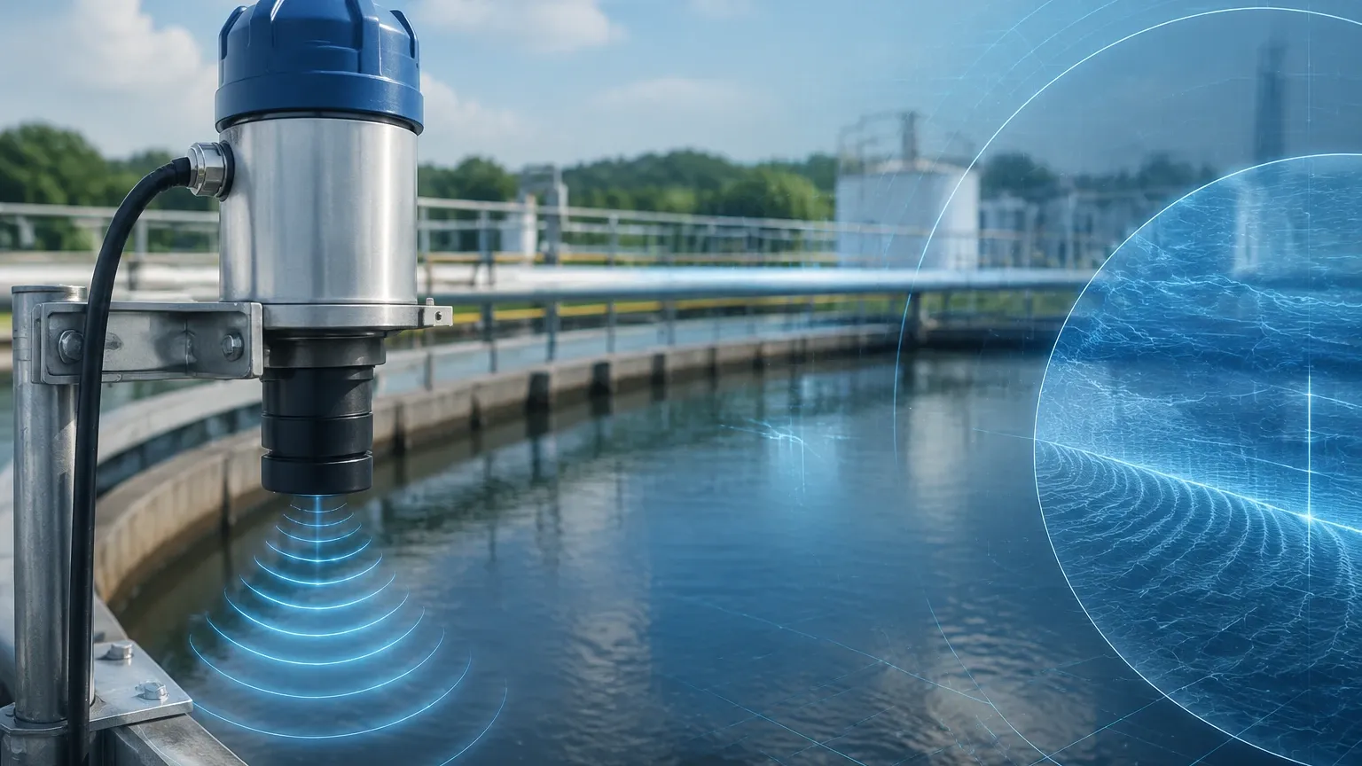
In many industrial water treatment and chemical applications, flow measurement is inextricably linked to level measurement. For instance, in open channel flow (such as flumes or weirs), an ultrasonic level sensor is used to measure the head height of the liquid. This height is then converted into a flow rate using standardized hydraulic equations.
Manufacturers like Welk provide integrated solutions where radar or ultrasonic level sensors work in tandem with flow transmitters to provide a holistic view of the fluid system. For more information on how these technologies integrate, you can Review product options and application support to find the right balance of sensors for your facility.
Limitations and Common Risks
While highly versatile, ultrasonic technology is not a universal solution. Engineers must be aware of the following limitations:
1. Entrained Air: Excessive bubbles can block the ultrasonic signal in transit-time meters, leading to "signal loss" errors.
2. Temperature Extremes: Rapid changes in fluid temperature can alter the speed of sound in the liquid. High-quality sensors include temperature compensation, but extreme heat may require specialized high-temperature transducers and coupling compounds.
3. Low Flow Cut-off: At extremely low velocities, the time difference (Δt) becomes so small that it approaches the noise floor of the electronics. Most sensors have a "low flow cut-off" setting to prevent false readings from thermal convection or vibration.
4. Coupling Agent Dry-out: For clamp-on sensors, the acoustic couplant (gel or grease) between the sensor and the pipe can dry out over several years, leading to signal degradation. Solid foil couplants are often recommended for long-term permanent installations.
Frequently Asked Questions (FAQ)
Q: Can ultrasonic flow sensors measure gas?
A: While this article focuses on liquid measurement, specialized ultrasonic gas flow meters do exist. They operate on the transit-time principle but require much higher-powered transducers and more sensitive electronics because sound travels differently through gas than through liquid.
Q: Do I need to recalibrate my clamp-on sensor if I move it to a different pipe?
A: Yes. The sensor must be programmed with the new pipe's outside diameter, wall thickness, material, and the specific fluid type. These parameters are critical for the internal processor to calculate the correct path length and flow velocity.
Q: How does pipe vibration affect the sensor?
A: Standard industrial vibrations usually do not affect the ultrasonic signal because the frequencies used for measurement (typically 0.5 MHz to 4 MHz) are much higher than mechanical vibration frequencies. However, extreme vibration can loosen mounting brackets or cause the coupling agent to migrate.
Q: What is the expected lifespan of a flow sensor ultrasonic?
A: Since there are no moving parts to wear out, the electronics and transducers can last 10 to 15 years or more, provided they are protected from environmental extremes and electrical surges.
Conclusion
The flow sensor ultrasonic represents a pinnacle of non-invasive measurement technology. By understanding the distinction between transit-time and Doppler methods and adhering to strict installation guidelines regarding pipe runs and transducer placement, industrial operators can achieve precise flow monitoring with minimal maintenance overhead. Whether for municipal water management, chemical dosing, or cooling water loops in power plants, these sensors provide the data necessary for efficient and safe process control. For those seeking to upgrade their current systems or design new installations, consulting with professional manufacturers ensures that the selected instrumentation meets the rigorous demands of the modern industrial environment.