Ispe Casa 2026
Ispe Casa 2026
The pharmaceutical and life sciences industries are governed by some of the most stringent regulatory and operational standards in the world. As we look toward ispe casa 2026, the focus on automation, precision, and hygienic design in process engineering has never been more critical. The ISPE Carolina-South Atlantic (CASA) Life Sciences Technology Show serves as a primary venue for professionals to evaluate the latest advancements in manufacturing technology. For engineers and facility managers, selecting the right level measurement instrumentation is a cornerstone of ensuring batch consistency, safety, and compliance with Good Manufacturing Practices (GMP).
In the lead-up to ispe casa 2026, understanding the fundamental physics behind level sensing and how these technologies integrate into pharmaceutical environments is essential for optimizing production lines. This guide explores the core measurement principles and selection criteria necessary for high-stakes industrial applications.
Fundamental Principles of Level Measurement
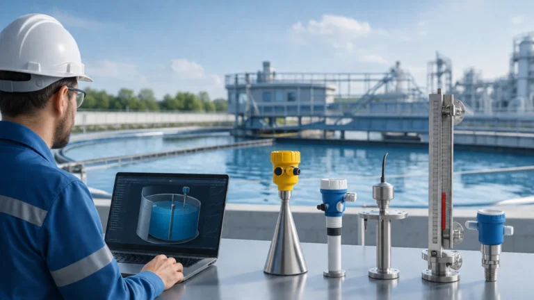
Before selecting a device for a pharmaceutical or chemical process, it is necessary to understand how different sensors interact with the medium and the vessel environment. In the context of the technologies often showcased at events like ispe casa 2026, four primary methods dominate the landscape.
Radar Level Measurement (Non-Contact)
Radar level meters operate on the Time of Flight (ToF) principle. The sensor emits a high-frequency microwave signal (often in the 26 GHz or 80 GHz range) toward the product surface. The signal reflects off the surface and returns to the antenna. The instrument calculates the distance based on the time interval between transmission and reception.
* Advantage: Being non-contact, it is highly hygienic and unaffected by changes in pressure, temperature, or vapor space composition.
* Pharma Relevance: 80 GHz radar technology allows for smaller antenna sizes, which are ideal for the compact vessels frequently used in biotech and pharmaceutical labs.
Ultrasonic Level Sensors
Similar to radar, ultrasonic sensors use ToF but employ sound waves instead of electromagnetic waves. A transducer emits an ultrasonic pulse that bounces off the liquid surface. The time taken for the echo to return is proportional to the distance.
* Advantage: Cost-effective and easy to install for atmospheric tanks.
* Limitation: Sound speed is affected by air temperature and gas composition, and the signal can be absorbed by heavy foam or dispersed by steam.
Hydrostatic Level Transmitters
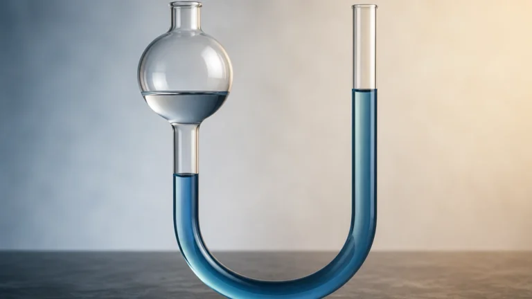
Hydrostatic measurement relies on the relationship between the height of a liquid column and the pressure it exerts at the base of the tank ($P = \rho \cdot g \cdot h$). A pressure sensor at the bottom of the vessel measures this force.
* Advantage: Highly reliable for vented or pressurized tanks when using differential pressure setups.
* Pharma Relevance: Flush-mounted diaphragms prevent "dead legs" where bacteria could proliferate, making them suitable for Clean-in-Place (CIP) environments.
Magnetic Level Gauges and Switches
Magnetic gauges use a float containing a permanent magnet that moves with the liquid level inside a bypass chamber. This magnet flips external rollers or triggers reed switches to provide visual or electronic feedback.
* Advantage: Provides a clear, local visual indication without requiring power.
* Pharma Relevance: Useful for auxiliary storage tanks (e.g., boiler feed water or bulk chemical storage) where redundant mechanical verification is required.
Selection Criteria for Life Science Applications
When preparing for infrastructure upgrades for ispe casa 2026, engineers must evaluate instruments based on specific pharmaceutical constraints. Unlike general industrial applications, the materials and design must withstand rigorous sterilization cycles.
1. Hygienic Design and Certifications: Instruments must often meet 3-A, EHEDG, or USP Class VI standards. For the Main Page of a facility's instrumentation strategy, ensuring that wetted parts are made of 316L stainless steel or high-grade PTFE is non-negotiable.
2. Surface Finish: To prevent microbial growth, wetted surfaces should have a surface roughness ($R_a$) of less than 0.8 μm, often achieved through electropolishing.
3. Process Connections: Standard threaded connections are often replaced by Tri-Clamp or aseptic flanges to ensure leak-proof and bacteria-free seals.
4. Resistance to CIP/SIP: The sensor must survive repeated exposure to caustic cleaning agents and saturated steam at temperatures up to 130°C (266°F) or higher.
Technology Selection Table
| Technology | Accuracy | Best For | Major Limitation | Hygienic Suitability |
| :— | :— | :— | :— | :— |
| 80 GHz Radar | ±1 mm | Small vessels, agitators | High dielectric constant needed | Excellent (Non-contact) |
| Ultrasonic | ±0.25% of range | Water storage, sumps | Affected by foam/steam | Good |
| Hydrostatic | ±0.1% of span | Constant density liquids | Density changes affect reading | Excellent (Flush mount) |
| Magnetic Gauge | ±5 mm | Visual backup, bypass | Moving parts subject to wear | Moderate |
Installation and Engineering Considerations
Proper installation is as critical as the technology choice itself. At ispe casa 2026, many discussions will likely center on the integration of these sensors into automated control systems (SCADA/DCS).
* Beam Angle and Obstructions: For radar and ultrasonic sensors, the beam must have a clear path to the liquid. Internal components like agitators, baffles, or heating coils can create false echoes. Modern radar units use "false echo suppression" software to map out these obstructions.
* Mounting Position: Sensors should generally not be mounted in the center of a tank (to avoid multiple reflections) or too close to the wall (to avoid interference). Ideally, the sensor is placed at 1/3 the radius of the tank.
* Dead Zones (Blocking Distance): Every ToF sensor has a "dead zone" directly beneath the transducer where measurements are impossible. This must be accounted for in the tank design to prevent overfilling.
* Reference Point: Always calibrate the "zero" point based on the lowest possible drain point of the vessel to ensure accurate inventory tracking.

Limitations and Common Challenges
Despite advancements in technology, certain physical conditions remain challenging for level measurement instruments:
1. Heavy Foam: In fermentation processes, thick foam can absorb ultrasonic signals and scatter radar waves. In these cases, hydrostatic or guided wave radar (GWR) may be preferred.
2. Vapor and Condensation: High-temperature processes create condensation on sensor faces. Some radar antennas are designed with convex PTFE covers to allow droplets to run off, preventing signal attenuation.
3. Vacuum Conditions: Ultrasonic sensors cannot operate in a vacuum because sound requires a medium to travel. Radar is the preferred choice for vacuum-rated reactors.
4. Agitation: Turbulent surfaces can cause signal jitter. Using damping filters in the transmitter software or installing the sensor inside a stilling well can stabilize the output.
Frequently Asked Questions (FAQ)
Q: Why is 80 GHz radar becoming the standard for pharmaceutical tanks?
A: The higher frequency results in a much narrower beam angle (as small as 3 degrees). This allows the signal to avoid internal tank obstructions like agitators and allows for installation on smaller nozzles, which are common in hygienic vessels.
Q: How does temperature affect hydrostatic level measurement?
A: While the pressure measurement itself is stable, liquid density changes with temperature. If the process temperature fluctuates significantly, the transmitter must be paired with a temperature sensor to provide a compensated level reading.
Q: Can ultrasonic sensors be used in CIP cycles?
A: Generally, no. The high-temperature steam used in Sterilization-in-Place (SIP) and the aggressive chemicals in CIP can damage the transducer face or exceed the sensor's temperature rating. Radar or flush-mount hydrostatic sensors are better suited for these environments.
Q: What is the significance of IO-Link in 2026 instrumentation?
A: IO-Link is a communication protocol that allows for bidirectional data exchange. It enables "smart" sensors to provide diagnostic data (like signal strength or internal temperature) directly to the PLC, facilitating predictive maintenance—a key theme for ispe casa 2026.
Preparing for the Future of Process Automation
As we approach ispe casa 2026, the convergence of digital transformation and precision engineering is clear. Level measurement is no longer just about knowing if a tank is full or empty; it is about data integrity, batch repeatability, and minimizing waste. For professionals looking to refine their facility's capabilities, reviewing current sensor performance against modern standards is the first step.
For more detailed technical specifications on radar, ultrasonic, and hydrostatic solutions tailored for industrial automation, you can Review product options and application support to ensure your systems meet the evolving demands of the life sciences sector. By selecting the correct measurement principle and adhering to rigorous installation standards, manufacturers can achieve the operational excellence required in the 2026 landscape.