Submersible Hydrostatic Level Transmitter
Submersible Hydrostatic Level Transmitter
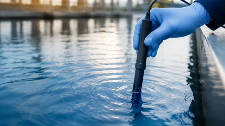
In the landscape of industrial process control, the submersible hydrostatic level transmitter stands as one of the most reliable and cost-effective instruments for continuous level monitoring. Unlike non-contact technologies that may struggle with foam, dust, or complex tank geometries, hydrostatic sensors utilize the fundamental laws of physics—specifically the relationship between pressure and liquid depth—to provide accurate data in diverse environments ranging from deep groundwater wells to industrial wastewater treatment plants.
For engineers and procurement professionals, selecting the right submersible hydrostatic level transmitter requires a deep understanding of the operating environment, the chemical properties of the media, and the physical constraints of the installation site. This guide provides a comprehensive technical overview of hydrostatic measurement, selection criteria, and practical installation strategies to ensure long-term operational success.
The Principle of Hydrostatic Level Measurement
The operation of a submersible hydrostatic level transmitter is based on the principle that the pressure at a specific point within a static liquid is proportional to the weight of the liquid column above that point. This is expressed by the hydrostatic pressure formula:
P = ρ · g · h
Where:
- P is the hydrostatic pressure (typically measured in Pascals or Bar).
- ρ (rho) is the density of the liquid (kg/m³).
- g is the acceleration due to gravity (approximately 9.81 m/s²).
- h is the height of the liquid column (meters).
Since gravity is a constant and the density of the liquid is usually known, the transmitter can calculate the height (h) by measuring the pressure (P).
Atmospheric Pressure Compensation
A critical component of the submersible hydrostatic level transmitter is the vented cable. Because the sensor is submerged, it is subjected to both the pressure of the liquid and the atmospheric pressure pressing down on the surface of the liquid. To ensure accuracy, the sensor must "ignore" changes in barometric pressure. This is achieved via a small breather tube (vent tube) located inside the transmitter's cable, which allows the back of the sensing diaphragm to be exposed to the ambient atmospheric pressure. This mechanical compensation ensures that the output signal represents only the pressure exerted by the liquid height.
Key Components and Construction
Welk industrial-grade transmitters are engineered to withstand prolonged submersion in harsh environments. The typical construction consists of three primary modules:
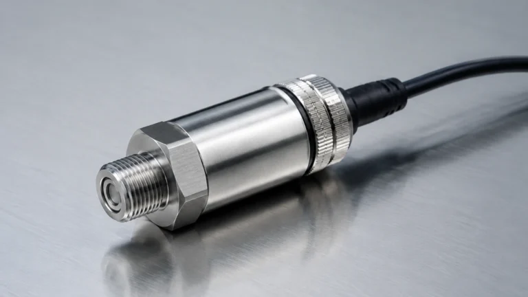
1. The Sensor Head: Usually made of 316L stainless steel, titanium, or specialized plastics like PTFE. It contains the sensing element, which is typically a piezo-resistive silicon chip or a ceramic capacitive diaphragm. Ceramic diaphragms are often preferred for abrasive or corrosive applications due to their high mechanical strength and chemical resistance.
2. The Submersible Cable: This is more than just an electrical conductor. It contains the power/signal wires, a high-strength tension member (such as Kevlar) to prevent stretching, and the atmospheric vent tube. Cable jacket materials are selected based on the media: Polyurethane (PUR) for general water, Polyethylene (PE) for drinking water, and Fluorinated Ethylene Propylene (FEP) or PTFE for aggressive chemicals.
3. The Signal Processing Unit: Located within the sensor body, this electronics package converts the raw millivolt signal from the diaphragm into a standard industrial output, such as 4-20mA, 0-10V, or digital protocols like RS485 Modbus and HART.
Selection Criteria for Industrial Applications
Choosing the correct submersible hydrostatic level transmitter involves balancing technical specifications with environmental realities. The following table provides a baseline for evaluating different models based on typical industrial scenarios.
Practical Selection Table
| Application Type | Recommended Housing | Cable Material | Typical Accuracy | Key Feature |
| :— | :— | :— | :— | :— |
| Clean Water/Reservoirs | 304 or 316L Stainless Steel | PUR or PE | ±0.25% FS | Cost-effective, long-term stability |
| Wastewater/Sewage | 316L Stainless Steel | PUR | ±0.5% FS | Non-clogging diaphragm design |
| Chemical Storage | PTFE or PVDF | FEP or PTFE | ±0.5% FS | High corrosion resistance |
| Deep Boreholes | 316L Stainless Steel | Reinforced PUR | ±0.1% to ±0.25% | High pressure rating, lightning protection |
| High Temperature | 316L with cooling fins | PTFE | ±0.5% FS | Specialized oil-filled sensors |
Evaluation Factors
- Measurement Range: Always specify the maximum depth. If a tank is 5 meters deep, a 0-6m or 0-10m range is appropriate to avoid overpressure during surge events.
- Media Density: If the liquid is not water (e.g., oil or concentrated brine), the transmitter must be calibrated for the specific density of that fluid. A fluid with a density of 1.2 g/cm³ will exert 20% more pressure than water at the same depth.
- Output Signal: 4-20mA is the industry standard for long-distance transmission (up to 1,000 meters) due to its noise immunity. For smart city or remote IoT applications, Modbus RS485 is often preferred for low power consumption and multi-parameter data.
For a detailed review of available sensor configurations and technical support, professionals should consult the Main Page to match specific project requirements with Welk's product capabilities.
Installation Guidelines and Best Practices
Proper installation is paramount to the longevity of a submersible hydrostatic level transmitter. Even the most robust sensor can fail if the cable is damaged or the vent tube is blocked.
1. Avoid Turbulence: The sensor should be installed in an area of the tank or well where the liquid is relatively calm. If installed near an inlet pipe or agitator, the moving liquid will create dynamic pressure, leading to erratic readings. In such cases, use a stilling well (a perforated pipe) to shield the sensor.
2. Cable Management: Never allow the cable to kink. When lowering the sensor into a deep well, use cable clamps to secure the cable to the discharge pipe at regular intervals. This prevents the weight of the cable from straining the internal vent tube or electrical connections.
3. Vent Tube Protection: The end of the cable (where the vent tube exits) must be located in a dry, moisture-free environment. If moisture enters the vent tube, it can migrate down to the sensor electronics, causing permanent damage. Use a specialized junction box with a breathable desiccant filter or a Gore-Tex vent to prevent water ingress while still allowing air pressure equalization.
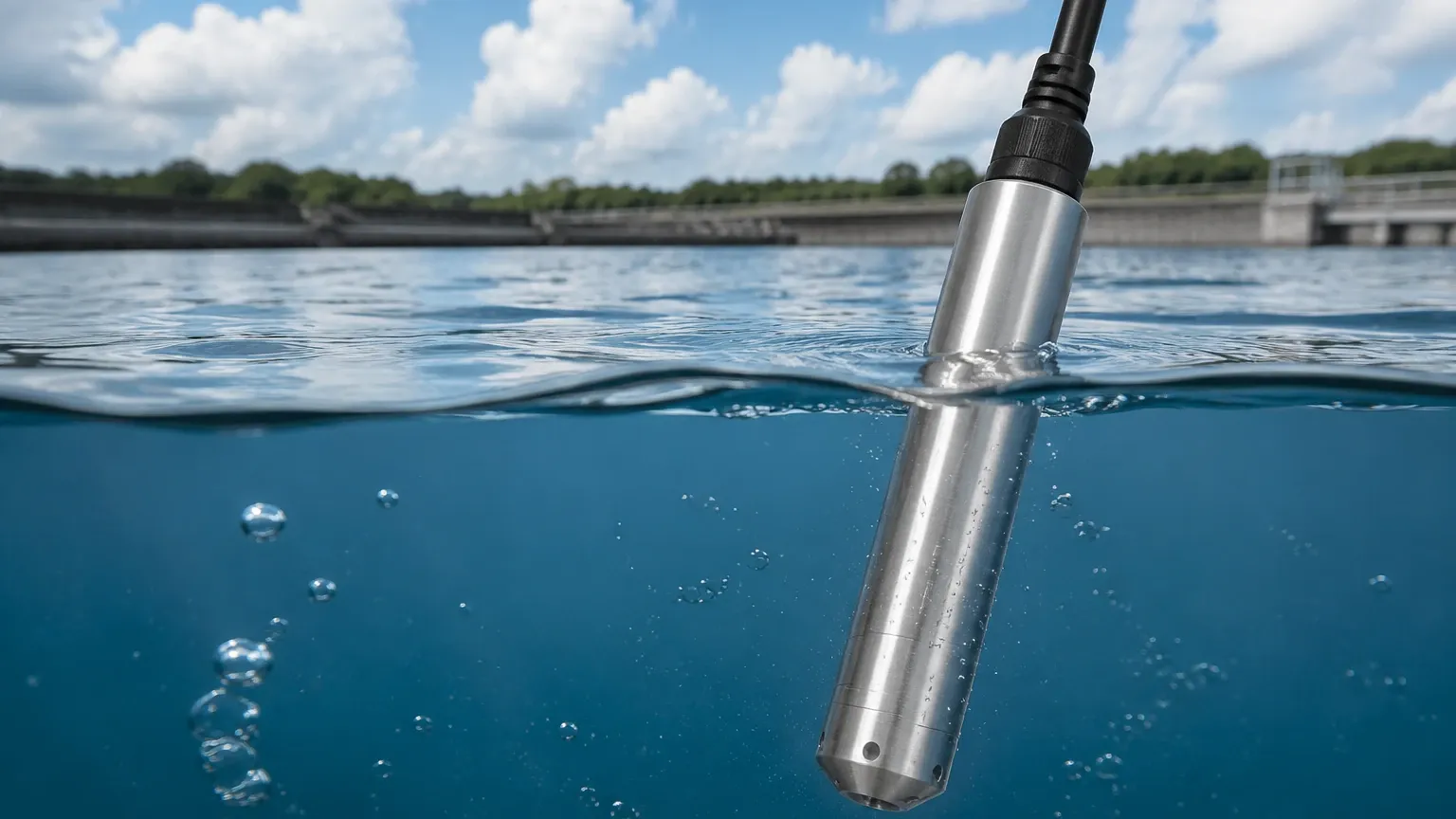
4. Positioning: The sensor should not rest directly on the bottom of a tank where silt or sediment can accumulate. This can block the pressure port or cause the diaphragm to become buried. Suspend the sensor approximately 100mm to 300mm (4 to 12 inches) above the floor.
Limitations and Environmental Constraints
While highly versatile, the submersible hydrostatic level transmitter is not a "one-size-fits-all" solution. Engineers must be aware of the following limitations:
- Density Sensitivity: Since the measurement is based on weight, any change in the liquid's density—caused by temperature fluctuations or changes in chemical concentration—will result in a measurement error. In applications with significant temperature swings, integrated temperature compensation or secondary temperature sensors are required.
- Pressurized Tanks: Submersible hydrostatic sensors are designed for vented (open to atmosphere) tanks. If the tank is pressurized or under vacuum, a submersible sensor will provide an incorrect reading because it cannot distinguish between the liquid's hydrostatic pressure and the gas pressure above it. In these cases, a differential pressure (DP) transmitter is required.
- Mechanical Damage: The sensing diaphragm is delicate. Avoid cleaning the sensor with sharp objects or high-pressure water jets, as this can deform the diaphragm and shift the calibration.
Maintenance and Troubleshooting
Under normal conditions, a high-quality hydrostatic transmitter requires very little maintenance. However, periodic checks are recommended to ensure system integrity.
- Visual Inspection: Check the cable jacket for signs of wear, chemical degradation, or cuts. Inspect the sensor head for mineral scaling or biological growth (algae), which can be gently cleaned with a soft brush and mild detergent.
- Zero-Point Verification: Periodically pull the sensor out of the liquid. The output should return to 4.00mA (for a 4-20mA system) or 0 on a digital display. If the zero point has shifted, it may indicate sediment buildup or diaphragm fatigue.
- Desiccant Replacement: If using a vented junction box with a desiccant pack, check the color of the silica gel. If it has turned from blue to pink (or orange to green), it is saturated and must be replaced to prevent moisture from entering the vent tube.
Frequently Asked Questions (FAQ)
Q: Can I cut the cable of a submersible level transmitter to fit my site?
A: Yes, most cables can be shortened, but it must be done carefully. You must ensure the vent tube is not crimped or blocked during the process. It is often better to coil excess cable neatly in a junction box rather than cutting it, as this preserves the factory-sealed termination.
Q: How does the sensor handle freezing conditions?
A: If the liquid freezes around the sensor, the expansion of the ice can crush the diaphragm. In climates where freezing is possible, the sensor should be installed below the frost line or equipped with a heating element in the stilling well.
Q: What is the maximum depth a hydrostatic sensor can measure?
A: Welk offers standard models for depths up to 200 meters (approx. 656 feet), with specialized borehole versions capable of reaching even greater depths. The limitation is usually the tensile strength of the cable and the pressure rating of the sensing element.
Q: Is a hydrostatic transmitter suitable for measuring sludge?
A: Yes, provided a "flush diaphragm" or "large-diameter" version is used. Standard sensors have a small pressure port that can easily clog with solids. A flush diaphragm design prevents material buildup and allows for easier cleaning.
By adhering to these engineering principles and selection guidelines, industrial operators can leverage the submersible hydrostatic level transmitter to achieve high-precision monitoring with minimal overhead. For further technical specifications or to request a quote for a customized measurement solution, visit the Main Page to explore the full range of Welk industrial instrumentation.