Vega 200
Vega 200
In the landscape of industrial process automation, achieving precise level measurement is a fundamental requirement for operational efficiency, safety, and inventory management. The introduction of compact radar technology, specifically exemplified by the vega 200 series (including the VEGAPULS 21, 22, and 23), has shifted the standard for liquid and solid level monitoring. These sensors leverage high-frequency radar signals to provide non-contact measurement in environments where traditional ultrasonic or hydrostatic methods might struggle. This guide explores the technical principles, application criteria, and installation best practices for the vega 200 series and similar high-frequency radar instruments.
Understanding the Measurement Principle: 80 GHz Radar
Before selecting a specific instrument like the vega 200, it is essential to understand the underlying physics of its operation. Most modern compact radar sensors operate on the Frequency Modulated Continuous Wave (FMCW) principle using the 80 GHz frequency band (W-band).
Time of Flight and FMCW
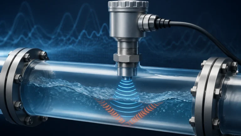
Radar sensors emit a continuous signal with a changing frequency. This signal is reflected by the surface of the medium and received by the antenna. Because the frequency of the emitted signal is constantly changing, there is a frequency difference between the emitted and the received signal. This difference is proportional to the time of flight, which allows the internal processor to calculate the distance to the product surface with millimeter precision.
The Advantage of 80 GHz Over 26 GHz
Older radar technologies typically operated at 26 GHz. The shift to 80 GHz in the vega 200 series offers several technical advantages:
1. Beam Focusing: Higher frequencies allow for much smaller antenna sizes while maintaining a narrow beam angle (often as low as 3° to 4°). This is critical in narrow tanks or vessels with internal obstructions like agitators or heating coils.
2. Signal Sensitivity: 80 GHz signals have a shorter wavelength, making them more sensitive to reflections from media with low dielectric constants (εr), such as plastic pellets or certain oils.
3. Accuracy: The wider bandwidth available at 80 GHz improves the resolution of the distance measurement, reducing the "noise" in the signal.
Technical Specifications of the Vega 200 Series
The vega 200 series is designed as a compact, cost-effective solution for standard applications in water treatment and general process industries. Below are the typical technical boundaries for these instruments.
| Feature | Specification (Typical) |
| :— | :— |
| Measuring Range | Up to 15m (49.2 ft) or 30m (98.4 ft) depending on model |
| Frequency | 80 GHz (W-band) |
| Accuracy | ±2 mm (0.079 in) |
| Process Temperature | -40°C to +80°C (-40°F to +176°F) |
| Process Pressure | -1 to 3 bar (-100 to 300 kPa) |
| Output Signal | 4…20 mA, HART, Modbus, or SDI-12 |
| Housing Material | PVDF / PBT (typically IP66/IP67 or IP68) |
These sensors are often utilized in simple storage tanks, open basins, or plastic IBCs where high-pressure or extreme-temperature ratings are not required, but high reliability is essential.
Practical Selection Criteria for Industrial Applications
When evaluating the vega 200 for a specific project, engineers must consider the chemical and physical properties of the medium, as well as the vessel geometry.
1. Media Characteristics
The dielectric constant (DK value) of the medium determines how much energy is reflected back to the sensor. Water has a high DK (~80) and is an excellent reflector. Hydrocarbons and dry solids have much lower DK values (~1.5 to 5). While the 80 GHz technology in the vega 200 handles low DK values better than older radar, very low-reflectivity materials may require a larger antenna or a more powerful sensor variant.
2. Surface Turbulence and Foam
Radar is generally superior to ultrasonic technology in the presence of foam. However, extremely dense, thick foam can still absorb radar signals. If a process involves heavy foam, the sensor should be mounted in a position where the foam is thinnest, or a stilling well should be considered.
3. Vessel Geometry
Because the vega 200 features a narrow beam, it can be installed closer to the tank wall than ultrasonic sensors. However, it is still vital to ensure that the signal path is clear of ladders, pipes, or inflow streams. For more complex industrial requirements, exploring a wide range of options on the Main Page can help identify if a standard radar or a specialized guided wave radar is more appropriate.
Installation Guidelines and Best Practices
Correct installation is the most significant factor in instrument longevity and measurement accuracy. For the vega 200 series, follow these engineering standards:
Mounting Position
* Avoid the Center: Do not mount the sensor in the exact center of a cylindrical tank, as multiple reflections from the tank walls can converge and create false signals.
* Distance from Wall: Maintain a minimum distance from the wall (typically 200mm or 8 inches) to avoid interference.
* Sensor Alignment: The sensor must be mounted perpendicular to the product surface. In applications involving solids (like grain or plastic pellets), an aiming flange may be needed to align the sensor with the material's angle of repose.
Nozzle Considerations
The radar signal must be able to leave the antenna without being reflected by the mounting nozzle. If the nozzle is too long or too narrow, it will create a "ringing" effect that blinds the sensor in the upper part of the tank. Ideally, the antenna should protrude slightly below the bottom of the nozzle.
Blocking Distance (Dead Zone)
Every radar sensor has a minimum distance it cannot measure (the dead zone). For the vega 200, this is typically very small (around 0mm to 50mm from the antenna face), but it must be accounted for in the tank's overflow protection logic.
Limitations and Environmental Considerations
While the vega 200 is a versatile tool, it is not a universal solution. Engineers should be aware of the following limitations:
* Pressure and Temperature: The compact PVDF housing of the vega 200 series is designed for moderate environments. It is not suitable for high-pressure reactors (above 3 bar) or high-temperature molten metal applications.
* Condensation: While 80 GHz radar can "see through" light condensation, heavy buildup of water droplets on the antenna face can attenuate the signal. Many vega 200 models feature a curved, "drip-off" antenna design to mitigate this, but in extreme cases, an air purge may be required.
* Dust: In solid applications, extreme dust can eventually coat the sensor face. While radar is far more resistant to dust than ultrasonic or optical sensors, periodic inspection is recommended in heavy-soiling environments.

Comparison: Radar vs. Ultrasonic Technology
In many B2B procurement scenarios, the vega 200 is compared against ultrasonic level sensors. The following table highlights why radar is increasingly preferred:
| Factor | Ultrasonic Sensors | Vega 200 Radar |
| :— | :— | :— |
| Medium | Affected by air density/temp | Unaffected by gas composition |
| Vacuum | Cannot function | Functions perfectly |
| Vapor/Steam | Significant signal loss | Minimal interference |
| Accuracy | Dependent on speed of sound | Constant (speed of light) |
| Mounting | Requires large clearance | Narrow beam allows tight mounting |
Maintenance and Digital Integration
One of the standout features of the vega 200 series is its integration with modern digital tools. Most units are equipped with Bluetooth connectivity, allowing for commissioning and diagnostics via a smartphone or tablet. This is particularly useful for sensors mounted on top of tall silos or in hazardous areas where physical access is restricted.
Diagnostic Data
Users can view the "echo curve" in real-time. This graphical representation shows the strength of the reflection from the product surface versus background noise. If a false reflection from a tank internal is detected, the software allows the user to perform a "false signal suppression," effectively telling the sensor to ignore that specific distance.
Frequently Asked Questions (FAQ)
Q: Can the vega 200 measure the level through a plastic tank wall?
A: Yes. Because radar signals can penetrate non-conductive materials, the vega 200 can be mounted above a plastic IBC or polyethylene tank and measure the liquid level inside without a hole being cut in the vessel.
Q: Is the vega 200 suitable for hazardous areas?
A: Yes, many versions of the vega 200 series come with ATEX, IECEx, and FM approvals for use in explosive atmospheres (Zone 0, 1, or 2).
Q: How does the sensor handle agitated surfaces?
A: The 80 GHz signal is very robust. Internal software algorithms (damping) can be adjusted to average out the fluctuations caused by waves or turbulence, providing a stable output signal.
Q: What is the power requirement?
A: These are typically two-wire, loop-powered devices (12-35V DC), making them easy to integrate into existing PLC or SCADA systems.
Conclusion
The vega 200 represents a significant advancement in making high-end radar technology accessible for everyday industrial applications. By understanding the 80 GHz principle and adhering to standard installation practices, facilities can achieve maintenance-free level measurement that outperforms older ultrasonic and mechanical systems. For engineers looking to compare these radar solutions with other technologies like hydrostatic transmitters or magnetic level gauges, visiting the Main Page provides a comprehensive overview of the available instrumentation landscape and technical support for specific application engineering.