Expansion Vessel for Solar
Expansion Vessel for Solar
In solar thermal engineering, managing the volumetric changes of heat transfer fluids is a critical safety and operational requirement. An expansion vessel for solar systems acts as a pressure-stabilizing component, accommodating the thermal expansion of the glycol-water mixture as it heats up within the solar collectors. Without a properly sized and monitored expansion system, solar circuits are prone to pressure spikes, fluid loss through pressure relief valves, and potential component failure due to stagnation temperatures.
For industrial-scale solar thermal applications—such as district heating, process heat for manufacturing, or large-scale hot water systems—the integration of expansion vessels must be paired with precise level and pressure monitoring. As a professional manufacturer of industrial level measurement instruments, Welk provides the sensing technologies required to ensure these systems remain within safe operational boundaries. This guide explores the principles, selection criteria, and monitoring requirements for solar expansion vessels in professional B2B environments.
Measurement Principles and System Dynamics
To understand the necessity of an expansion vessel for solar, one must first understand the physics of the closed-loop solar circuit. Most solar thermal systems utilize a mixture of water and propylene glycol to prevent freezing. This fluid has a specific coefficient of thermal expansion.
Thermal Expansion Mechanics
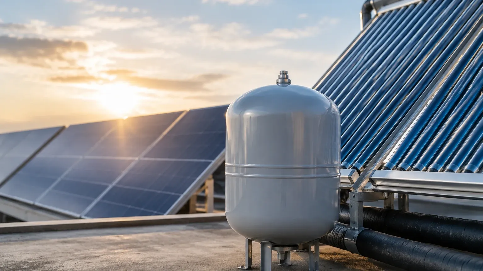
As the solar collectors absorb irradiance, the fluid temperature rises. In industrial solar arrays, temperatures can fluctuate from ambient night-time levels to over 200°C (392°F) during stagnation events. Since liquids are largely incompressible, the increase in volume must be accommodated. The expansion vessel contains a flexible diaphragm or bladder that separates a nitrogen gas cushion from the solar fluid. When the fluid expands, it enters the vessel and compresses the gas cushion, keeping the system pressure within a controlled range.
The Importance of Level Monitoring
While the expansion vessel handles the physical volume change, monitoring the fluid level within the wider system—particularly in buffer tanks or large-scale pressurized reservoirs—is essential. In large industrial solar plants, level measurement instruments such as hydrostatic transmitters or ultrasonic sensors are used to:
1. Detect Leaks: A gradual drop in the baseline fluid level (at a normalized temperature) indicates a leak in the circuit.
2. Prevent Dry Running: Ensuring the pump intake always has sufficient head pressure.
3. Automate Refilling: Coordinating with make-up water/glycol stations to maintain the minimum static pressure.
For those designing high-capacity systems, reviewing advanced sensing options on the Main Page can provide insights into how to integrate automated monitoring with expansion management.
Key Evaluation Criteria for Solar Expansion Vessels
Selecting an expansion vessel for solar applications differs significantly from standard HVAC or potable water heating. The following criteria are mandatory for industrial-grade specifications.
1. Temperature Resistance
Solar fluids can reach extreme temperatures, especially if the system loses power and enters a "stagnation" state (where the fluid turns to steam in the collectors). The vessel's membrane must be rated for continuous exposure to high temperatures—typically up to 70°C (158°F) at the vessel connection, though intermediate cooling vessels (discharge vessels) are often used to protect the membrane if the return temperature exceeds this limit.
2. Membrane Material
Standard EPDM membranes used in domestic heating may not withstand the chemical properties of concentrated glycol at high temperatures. High-grade Butyl or specialized solar-rated membranes are required to prevent premature degradation and gas permeation.
3. Pressure Ratings
Industrial solar circuits often operate at higher static pressures to raise the boiling point of the fluid. The expansion vessel must have a maximum working pressure (MWP) that exceeds the setting of the system's safety relief valve (SRV), typically 6 bar, 10 bar, or higher in specialized process heat applications.
Sizing and Selection Table
Correct sizing is the most common point of failure in solar system design. The vessel must be large enough to handle the total expansion volume ($V_e$) plus a water seal ($V_{wr}$) to ensure the system remains pressurized even when cold.
| Parameter | Description | Typical Industrial Range |
| :— | :— | :— |
| Total System Volume ($V_s$) | Sum of collectors, piping, and heat exchangers. | 100L to 5,000L+ |
| Expansion Coefficient ($n$) | Based on max temperature and glycol % | 7% to 13% |
| Pre-charge Pressure ($P_0$) | Gas pressure before fluid entry. | Static height + 0.5 bar |
| Final Pressure ($P_e$) | Max allowed pressure (SRV – 10%). | 3.0 to 9.0 bar |
| Efficiency Factor ($K$) | Ratio of usable volume to total vessel volume. | 0.4 to 0.6 |
Basic Sizing Formula:
$$V_n = \frac{V_e + V_{wr}}{K}$$
Where $V_n$ is the nominal volume of the required expansion vessel.
Installation Considerations for Industrial Systems
Proper installation ensures the longevity of both the expansion vessel and the level measurement instrumentation.
* Point of No Pressure Change: The expansion vessel should ideally be connected to the suction side of the circulation pump. This ensures that the pump's differential pressure is added to the system pressure rather than subtracted from it, preventing cavitation.
* Orientation: Most solar vessels should be installed with the water connection at the top or side to prevent air from becoming trapped in the fluid chamber, which can lead to corrosion and inaccurate pressure readings.
* Intermediate Vessels: If the distance between the solar array and the expansion vessel is short, or if the system volume is high, an intermediate "cooling" vessel should be installed. This vessel acts as a thermal buffer to protect the expansion vessel's diaphragm from steam or high-temperature glycol.
* Integration with Level Sensors: In large-scale systems, a hydrostatic level transmitter can be installed at the base of the expansion line to provide a real-time digital readout of the fluid head, allowing operators to monitor system volume via a PLC or SCADA system.
Common Risks and Limitations
Failure to maintain or correctly specify an expansion vessel for solar leads to several operational risks:
1. Membrane Rupture: Over time, the nitrogen pre-charge can leak through the membrane (permeation) or the membrane can fail due to thermal stress. This results in a "waterlogged" tank, where the system has no room for expansion, leading to frequent safety valve discharges.
2. Corrosion: If the pre-charge is lost and oxygen enters the system during maintenance, internal corrosion can accelerate. Monitoring the system with high-quality level switches can provide early warning of fluid loss.
3. Stagnation Damage: In solar applications, if the vessel is undersized, the pressure rise during stagnation can exceed the vessel's limits, causing permanent deformation or system-wide fluid loss.
Monitoring and Maintenance Checklist
To ensure the reliability of the expansion system, industrial operators should follow a strict maintenance schedule:
* Annual Pre-charge Check: Isolate the vessel from the system, drain the fluid side, and check the nitrogen pressure. It should match the design pre-charge pressure.
* Fluid Level Verification: Use level measurement instruments to ensure the system hasn't lost fluid. A consistent level at a set temperature is the best indicator of a sealed system.
* Visual Inspection: Check for signs of glycol leakage at the valve stem or the connection point.
* Sensor Calibration: If using hydrostatic or radar level meters in the storage tanks, ensure they are calibrated to account for the specific gravity of the glycol mix, which changes with temperature.
Frequently Asked Questions (FAQ)
Q: Can I use a standard heating expansion vessel for a solar system?
A: No. Standard heating vessels are usually rated for lower temperatures (max 90°C at the source, but much less at the membrane) and may not be compatible with glycol. Solar-specific vessels feature high-temperature membranes and higher pressure ratings.
Q: How do I know if my expansion vessel has failed?
A: The most common sign is a rapid pressure increase when the solar pump starts or when the sun comes out, followed by a pressure drop to zero when the system cools. You can also depress the Schräder valve on the gas side; if fluid comes out, the membrane is ruptured.
Q: Why is nitrogen used for the pre-charge instead of compressed air?
A: Nitrogen is dry and inert. It reduces internal corrosion of the vessel shell and maintains pressure more stably than compressed air, which contains moisture and oxygen that can permeate the membrane faster.
Q: What role do level meters play in expansion management?
A: In large B2B and industrial solar installations, the expansion vessel is part of a larger fluid management strategy. Level meters (like those found on the Main Page) monitor the inventory in buffer tanks and detect if the expansion system is failing to keep the circuit full, providing an automated layer of protection that pressure gauges alone cannot offer.
Conclusion
The expansion vessel for solar is a fundamental component for pressure control, but its effectiveness depends on correct sizing, appropriate material selection, and robust monitoring. For industrial applications where system uptime and safety are paramount, integrating high-quality level measurement instruments ensures that expansion dynamics are managed proactively. By understanding the principles of thermal expansion and implementing precise sensing technologies, engineers can design solar thermal systems that are both efficient and resilient against the extremes of solar stagnation and seasonal temperature shifts.