Radar Level Transmitter Endress Hauser
Radar Level Transmitter Endress Hauser: An Engineering Guide to Selection and Application
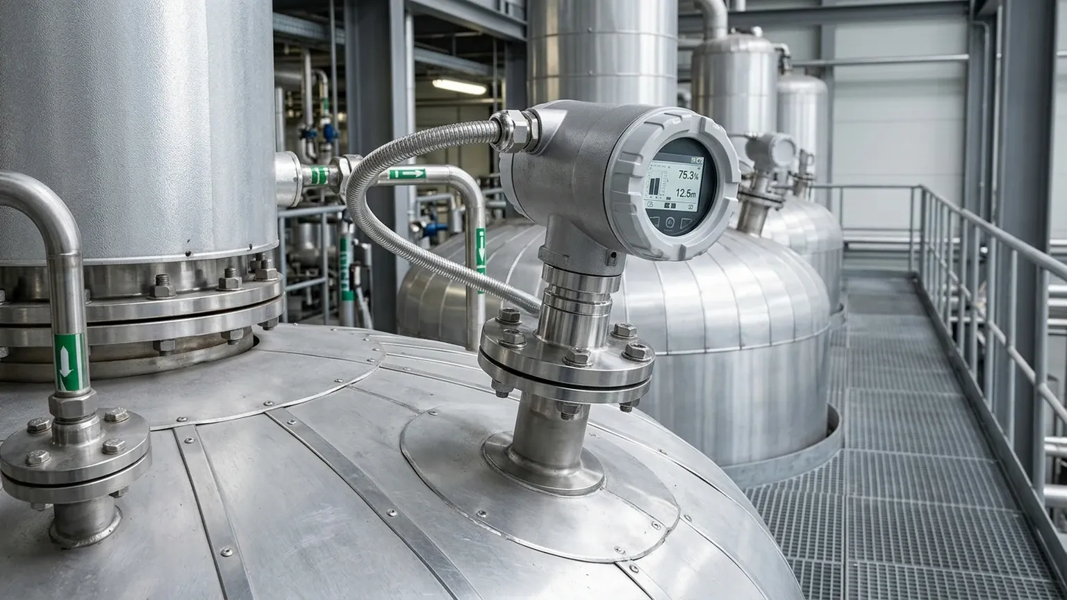
In the landscape of industrial process automation, non-contact level measurement has become the preferred standard for high-accuracy and low-maintenance requirements. Among the leading technologies in this field, the radar level transmitter endress hauser—specifically the Micropilot series—represents a benchmark for reliability in challenging environments. This guide examines the technical principles, selection criteria, and installation requirements for these instruments, providing engineers with the data necessary to integrate Radar Level Meters into complex industrial systems.
1. Fundamental Measurement Principles
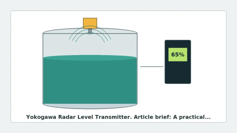
Radar level transmitters operate on the principle of Time of Flight (ToF). The device emits high-frequency electromagnetic pulses (typically in the GHz range) toward the surface of the medium. These pulses are reflected by the product surface and received by the sensor's antenna. The distance to the product surface is proportional to the time it takes for the pulse to travel to the surface and back.
Pulse Radar (PTOF) vs. FMCW
Industrial radar transmitters generally utilize one of two modulation techniques:
* Pulse Time of Flight (PTOF): The transmitter sends short microwave pulses and measures the elapsed time until the echo is received. This method is energy-efficient and suitable for many standard liquid applications.
* Frequency Modulated Continuous Wave (FMCW): The transmitter emits a continuous signal with a constantly changing frequency. The difference between the emitted frequency and the received frequency at any given moment is proportional to the distance. FMCW is often used in 80 GHz high-frequency sensors, offering superior resolution and a narrower beam angle, which is critical for avoiding internal tank obstructions.
2. Technical Specifications and Selection Criteria
Choosing the correct radar level transmitter endress hauser requires a detailed analysis of the process medium, the vessel geometry, and the environmental conditions. The Micropilot range is segmented by frequency and application type.
Key Selection Parameters
1. Dielectric Constant ($ε_r$): The reflectivity of the medium depends on its dielectric constant. Water has a high $ε_r$ (~80), making it easy to detect. Hydrocarbons and oils have low $ε_r$ (1.4 to 2.5), which may require high-sensitivity electronics or guided wave radar if the surface is turbulent.
2. Frequency (6 GHz, 26 GHz, 80 GHz):
* Low Frequency (6 GHz): Better suited for applications with heavy foam or steam, as longer wavelengths penetrate these disturbances more effectively.
* High Frequency (80 GHz): Offers a very narrow beam angle (as small as 3°), allowing for installation in tall, narrow nozzles and avoiding reflections from agitators or heating coils.
3. Process Temperature and Pressure: Standard units typically handle up to 130°C and 3 bar, but specialized high-temperature versions can withstand up to 450°C and pressures up to 160 bar (16 MPa).
Selection Table: Radar Technology Comparison
| Feature | 26 GHz Radar (Standard) | 80 GHz Radar (High Precision) | Guided Wave Radar (GWR) |
| :— | :— | :— | :— |
| Typical Application | General liquid storage | Tall silos, narrow tanks | Low $ε_r$ liquids, interface |
| Beam Angle | 8° to 20° | 3° to 4° | N/A (Contacting) |
| Max Range | Up to 35 m | Up to 125 m | Up to 45 m |
| Accuracy | ±2 mm | ±0.5 mm to ±1 mm | ±2 mm |
| Foam Resistance | Moderate | Low (Signal scattering) | High |
| Nozzle Sensitivity | Moderate | Low | High (Requires bypass) |
3. Installation Best Practices and Constraints
Proper physical installation is the most critical factor in ensuring the long-term accuracy of Radar Level Meters. Incorrect placement can lead to "false echoes" from tank internals, resulting in erratic readings.
Nozzle Considerations
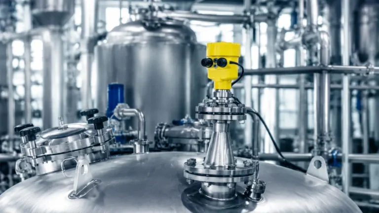
The antenna should ideally extend beyond the bottom of the mounting nozzle to prevent signal interference from the nozzle edge. If the nozzle is long, a high-frequency (80 GHz) transmitter is recommended because the narrow beam reduces the risk of the signal hitting the nozzle wall.
Positioning and Obstructions
* Avoid the Center: Do not mount the radar in the exact center of a cylindrical tank. Multiple reflections from the tank walls can converge at the center, creating a false high-level signal.
* Distance from Wall: The sensor should be mounted at a distance of at least 1/6th of the tank diameter from the wall to avoid interference from wall weld seams or buildup.
* Obstruction Clearance: Ensure the radar beam path is clear of ladders, agitators, and fill streams. If an agitator is present, the transmitter's software must be configured with an "envelope curve" to map out and ignore these static or periodic reflections.
Blocking Distance (Dead Zone)
Every radar transmitter has a blocking distance (typically 50 mm to 200 mm from the antenna tip). Level measurement is not possible within this zone. Engineers must ensure the maximum fill level of the tank does not enter the blocking distance to avoid signal loss.
4. Application Risks and Limitations
While radar technology is highly versatile, certain process conditions can compromise performance.
1. Heavy Foam: Dense, thick foam can absorb or scatter the radar signal. In such cases, 6 GHz sensors or guided wave radar (where the probe penetrates the foam) are more reliable than free-space 80 GHz units.
2. Turbulent Surfaces: Rapidly moving or boiling liquids scatter the signal. This can be mitigated through software averaging (damping) or by installing the radar inside a stilling well or bypass pipe.
3. Condensation and Buildup: While many modern antennas feature PTFE coatings to shed droplets, heavy condensation or crystalline buildup on the antenna can attenuate the signal. Integrated air purge connections are often used to keep the antenna face clean in dusty or humid environments.
4. Vacuum Conditions: Radar waves do not require a medium to travel, so they work perfectly in a vacuum. However, the mechanical seals of the transmitter must be rated for vacuum service to prevent air ingress or sensor damage.
5. Maintenance and Diagnostic Features
Modern radar level transmitter endress hauser units often include advanced diagnostic suites, such as Heartbeat Technology. These systems allow for:
* In-situ Verification: The device can perform self-diagnostics without interrupting the process, providing a report that complies with ISO 9001 quality requirements.
* Build-up Detection: The transmitter monitors the signal strength (amplitude) of the antenna reflection to predict when cleaning is required.
* Foam Detection: By analyzing the signal-to-noise ratio, the transmitter can alert operators to the presence of foam before it causes a measurement error.
6. Frequently Asked Questions (FAQ)
Q: Can a radar level transmitter measure the interface between two liquids?
A: Free-space radar is generally not suitable for interface measurement as the signal reflects off the top layer. Guided Wave Radar (GWR) is the standard choice for interface applications, provided the upper liquid has a lower dielectric constant than the lower liquid.
Q: Is 80 GHz always better than 26 GHz?
A: Not necessarily. While 80 GHz offers better focus and accuracy, 26 GHz is often more robust in applications with heavy dust or steam where the shorter wavelength of 80 GHz might suffer from more signal attenuation.
Q: How do I handle measurement in a plastic tank?
A: Radar signals can penetrate plastic. It is possible to mount a radar transmitter *above* a plastic tank and measure through the roof, provided the roof material is non-conductive and not too thick. However, this requires careful calibration to account for the signal attenuation caused by the plastic.
Q: What is the impact of heavy dust in solids measurement?
A: For solids, 80 GHz radar is highly effective because it can handle the steep angles of repose of the material. While dust can attenuate the signal, high-power 80 GHz transmitters are usually capable of penetrating standard dust clouds found in grain or cement silos.
7. Conclusion
The integration of a radar level transmitter endress hauser into an industrial process provides a high degree of precision and safety. By understanding the dielectric properties of the medium and the geometric constraints of the vessel, engineers can select a frequency and mounting strategy that minimizes downtime. For most modern liquid applications, the shift toward 80 GHz technology offers the easiest installation and highest resolution, though specialized cases involving foam or extreme steam still require the technical nuances of lower-frequency or guided-wave solutions.