Disadvantages of Radar Level Transmitter
Disadvantages of Radar Level Transmitter: An Engineering Guide to Limitations and Selection
In the landscape of industrial process control, radar level transmitters have become a dominant technology for non-contact measurement. Their ability to operate in vacuums, high pressures, and extreme temperatures makes them a preferred choice over ultrasonic or hydrostatic sensors in many scenarios. However, no single measurement technology is a universal solution. To ensure process reliability and safety, engineers must understand the specific constraints and the technical disadvantages of radar level transmitter systems.
Selecting the right Radar Level Meters requires a balance between technical capability and application-specific physics. This guide explores the fundamental operating principles of radar technology and provides a detailed analysis of the limitations that can impact performance in industrial environments.
Measurement Principles: How Radar Works
Before addressing the limitations, it is essential to understand the physics of the measurement. Radar level transmitters function based on the Time of Flight (ToF) principle using electromagnetic waves, typically in the microwave spectrum (6 GHz to 80 GHz).
Pulse Radar vs. FMCW
There are two primary methods used in modern industrial radar:
1. Pulse Radar: The transmitter emits a series of short microwave pulses. These pulses travel at the speed of light, reflect off the surface of the medium, and return to the sensor. The distance is calculated based on the time delay between emission and reception.
2. FMCW (Frequency Modulated Continuous Wave): The transmitter emits a continuous signal with a constantly changing frequency. The difference in frequency between the emitted signal and the reflected signal (the "beat frequency") is directly proportional to the distance. FMCW is generally more accurate and provides better signal-to-noise ratios in complex environments.
The Role of the Dielectric Constant ($ε_r$)
The success of a radar measurement depends on the Dielectric Constant (DK) of the material being measured. The DK is a measure of a substance's ability to reflect electromagnetic energy. Materials with high DK values (e.g., water, $ε_r ≈ 80$) reflect signals strongly. Materials with low DK values (e.g., hydrocarbons, solvents, or liquefied gases, $ε_r < 2.0$) allow much of the energy to pass through, resulting in a weak return signal.
Primary Disadvantages of Radar Level Transmitters
While radar is highly versatile, several factors can compromise its accuracy or render it unsuitable for specific applications. Understanding these disadvantages is critical for avoiding measurement failure.
1. Sensitivity to Low Dielectric Constants
The most significant technical limitation is the dielectric constant of the process medium. If the material has a very low DK (typically below 1.4 or 1.5), the radar signal may pass through the product and reflect off the bottom of the tank instead of the surface. This leads to a "loss of echo" or an incorrect reading of the tank bottom. While high-frequency 80 GHz transmitters have improved sensitivity, extremely low DK fluids still pose a challenge for non-contact radar.
2. Surface Conditions: Foam and Turbulence
Radar waves are susceptible to scattering and absorption at the surface of the liquid:
* Foam: The impact of foam depends on its density and conductivity. Thick, dense, or conductive foam (wet foam) can absorb the radar signal entirely, preventing a return echo. Light, airy foam (dry foam) may be transparent to the radar, causing it to measure the liquid level beneath the foam, which may or may not be the desired outcome.
* Turbulence: Rapidly moving or agitated surfaces cause the radar signal to scatter in multiple directions. While software algorithms can filter some of this noise, extreme turbulence can result in a weak or unstable signal return.
3. Mechanical Obstructions and Beam Angle
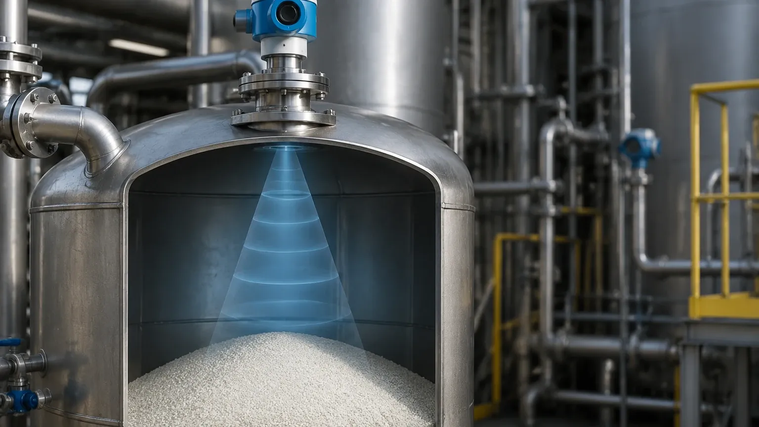
Radar signals propagate in a cone shape. Any internal structure within this cone—such as agitators, ladders, heating coils, or stay bolts—will create "false echoes."
* False Echo Mapping: While modern transmitters allow for "background subtraction" to ignore these fixed obstacles, the presence of an agitator blade moving through the beam path can still cause intermittent signal interference.
* Beam Angle: Lower frequency radars (e.g., 6 GHz or 26 GHz) have wider beam angles, requiring larger clear paths. If a tank is narrow or crowded, these units are often unsuitable.
4. High Initial Capital Expenditure (CAPEX)
Compared to ultrasonic sensors, hydrostatic pressure transmitters, or float switches, radar level transmitters represent a higher initial investment. The sophisticated electronics, high-frequency oscillators, and signal processing required for accurate radar measurement contribute to a higher price point. For simple water storage or non-critical applications, the cost-to-benefit ratio of radar may be difficult to justify.
5. Installation Constraints (The "Dead Zone")
Every radar transmitter has a "blocking distance" or "dead zone" immediately below the antenna (typically 50 mm to 500 mm depending on the model). Measurement is not possible within this zone. If a tank must be filled to the absolute top, the nozzle height must be carefully engineered to ensure the dead zone remains above the maximum fill level.
6. Signal Attenuation from Condensation and Buildup
While radar is generally better at handling vapor than ultrasonic technology, heavy condensation or material buildup on the antenna itself can attenuate the signal. If the medium is viscous or prone to crystallization (e.g., bitumen or certain chemical resins), the coating on the antenna lens can lead to measurement errors or total signal loss, necessitating frequent maintenance or the use of air purging systems.
Technical Comparison: Radar vs. Alternative Technologies
To better understand when the disadvantages of radar level transmitter systems outweigh the benefits, consider the following comparison table:
| Feature | Non-Contact Radar | Guided Wave Radar (GWR) | Ultrasonic | Hydrostatic Pressure |
| :— | :— | :— | :— | :— |
| Measurement Style | Non-contact | Contact (Probe) | Non-contact | Contact (Diaphragm) |
| Accuracy | High (±1mm to ±3mm) | Very High (±2mm) | Moderate (±0.25% of range) | Moderate (±0.1% to 0.5%) |
| Foam Tolerance | Moderate | High | Low | High |
| DK Dependency | High | Moderate | None | None |
| Vacuum Suitability | Excellent | Excellent | Poor | Excellent |
| Relative Cost | High | Medium-High | Low | Medium |
| Maintenance | Low | Moderate (Probe cleaning) | Low | Moderate (Clogging) |
Installation Considerations and Best Practices
To mitigate the disadvantages mentioned above, precise installation is required. Engineers should follow these guidelines:
1. Nozzle Geometry: The nozzle should be as short as possible. If a nozzle is too long or narrow, the radar signal will reflect off the nozzle walls (ringing), creating interference in the near-range measurement.
2. Orientation: The transmitter must be mounted vertically. Even a slight tilt can cause the signal to reflect away from the sensor, especially on flat liquid surfaces.
3. Avoid the Center: In cylindrical tanks with domed tops, do not mount the radar in the exact center. The parabolic shape of the tank roof can focus multiple reflections back to the sensor, causing signal noise.
4. Stilling Wells: For applications with heavy foam or extreme turbulence, installing the radar inside a stilling well (a vertical pipe) can provide a calm surface and a stronger signal, though this increases installation cost and maintenance requirements.
When to Avoid Non-Contact Radar
There are specific scenarios where an alternative technology is technically superior:
* Extremely Low Dielectric Media in Small Tanks: If the DK is < 1.4 and the tank is shallow, Guided Wave Radar (GWR) is preferred because the probe concentrates the energy, allowing for better reflection from low-DK materials.
* Heavy, Conductive Foam: In applications like large-scale fermentation or certain wastewater treatments where thick foam is constant, hydrostatic pressure or GWR with a coated probe often performs more reliably.
* Budget-Constrained Non-Critical Liquid Storage: For simple ambient-pressure water tanks, ultrasonic sensors provide a more cost-effective solution without the complexity of radar electronics.
Frequently Asked Questions (FAQ)
Q: Can radar level transmitters measure solids?
A: Yes, but with caveats. Solids like powders and grains have an angle of repose that tilts the reflecting surface away from the sensor. High-frequency (80 GHz) radar is typically required for solids to ensure a narrow beam and sufficient signal return.
Q: Does temperature or pressure affect radar accuracy?
A: No. Unlike ultrasonic waves, which depend on the speed of sound (affected by air density), radar waves are electromagnetic. They are virtually unaffected by changes in temperature, pressure, or the presence of vapors/gases in the tank headspace.
Q: How do I handle heavy dust in a silo?
A: While radar can penetrate dust better than light-based systems, extreme dust can still attenuate the signal. Using a radar with a lens antenna and an integrated air purge connection is the standard engineering solution for high-dust environments.
Q: Why is 80 GHz radar considered better than 26 GHz?
A: Higher frequency allows for a much narrower beam angle (as small as 3 degrees). This makes it easier to avoid internal obstructions and allows for installation on smaller nozzles. However, higher frequency units can be more sensitive to heavy condensation on the lens.
Conclusion
Radar level transmitters are powerful tools for modern industrial automation, offering high precision and reliability in challenging process conditions. However, the disadvantages of radar level transmitter systems—such as sensitivity to dielectric constants, susceptibility to heavy foam, and higher costs—must be factored into the engineering design phase. By understanding the physics of the measurement and the specific constraints of the vessel, process engineers can select the most appropriate instrument, ensuring long-term operational stability and accurate inventory management.