Temperature Transmitter
Temperature Transmitter
In the landscape of industrial automation and process control, the accurate measurement of temperature is as fundamental as the measurement of level, pressure, or flow. While sensors like Resistance Temperature Detectors (RTDs) and thermocouples are responsible for sensing thermal changes, the temperature transmitter is the critical component that translates these raw physical signals into a standardized format suitable for long-distance transmission and control system integration.
For engineers and plant managers, understanding the nuances of temperature transmitters is essential for maintaining process stability, ensuring safety, and optimizing efficiency. This guide explores the principles, types, and selection criteria for temperature transmitters, with a specific focus on their integration within industrial systems alongside level measurement technologies.
Measurement Principles and Signal Conversion
To understand how a temperature transmitter functions, one must first look at the primary sensors it supports. The two most common sensors used in industrial environments are RTDs and thermocouples. Each operates on a distinct physical principle, and the transmitter must be configured to interpret these specific signals correctly.
Resistance Temperature Detectors (RTDs)
RTDs, most commonly the Pt100 or Pt1000 varieties, operate on the principle that the electrical resistance of a metal (usually platinum) increases predictably as temperature rises. A Pt100 sensor, for instance, has a resistance of 100 ohms at 0°C. The temperature transmitter provides a small excitation current to the RTD and measures the resulting voltage drop. Because the resistance of the lead wires can introduce errors, transmitters often use 3-wire or 4-wire configurations to compensate for lead resistance, ensuring high accuracy over long distances.
Thermocouples
Thermocouples consist of two dissimilar metal wires joined at one end (the sensing junction). Based on the Seebeck effect, a small voltage is generated when there is a temperature difference between the sensing junction and the reference junction (the connection point at the transmitter). The transmitter measures this millivolt signal and applies "cold junction compensation" (CJC) to account for the temperature at the transmitter terminals, converting the raw voltage into a temperature reading.
The Role of the Transmitter
The temperature transmitter serves three primary functions: signal conditioning, linearization, and amplification. Raw signals from sensors are often weak and susceptible to electromagnetic interference (EMI). The transmitter converts these signals into a robust 4-20mA analog loop or a digital protocol such as HART, Modbus, or PROFIBUS. This allows the signal to travel hundreds of meters to a PLC or DCS without significant degradation.
Types of Temperature Transmitters
Transmitters are categorized by their mounting style and housing, which dictates where they can be deployed within a facility.
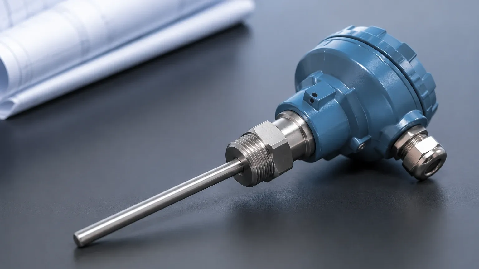
1. Head-Mount Transmitters: These are designed to fit directly inside the connection head of a temperature sensor assembly. This proximity to the sensor minimizes the length of low-level signal wiring, reducing the risk of noise interference. They are compact and cost-effective for localized measurements.
2. DIN-Rail Mount Transmitters: These are installed on standard 35mm rails inside a control cabinet or junction box. They are ideal for applications where multiple sensors are routed to a central location, allowing for easy maintenance in a clean environment.
3. Field-Mount Transmitters: These units are housed in rugged, often explosion-proof or weather-proof enclosures (e.g., NEMA 4X or IP67). They are used in the most demanding environments, such as offshore platforms or chemical processing plants, where the electronics must be protected from corrosive atmospheres and mechanical stress.
The Critical Link: Temperature and Level Measurement
In many industrial applications, temperature measurement is not an isolated task but a necessary input for accurate level measurement. As a professional manufacturer of industrial instruments, Welk provides solutions where these two parameters intersect to ensure process integrity. You can explore these integrated solutions on our Main Page.
Hydrostatic Level Compensation
In hydrostatic level measurement, the transmitter measures the pressure exerted by a liquid column. However, the density of a liquid changes with its temperature. For example, as water or oil heats up, it expands and its density decreases. Without a temperature transmitter providing real-time data to the control system, a hydrostatic sensor might report an incorrect level because the pressure has changed even though the mass of the liquid remains the same.
Ultrasonic and Radar Level Accuracy
For ultrasonic level sensors, temperature is a primary variable because the speed of sound through air is highly dependent on temperature. Most ultrasonic sensors include an integrated temperature sensor, but in large tanks with temperature gradients, external temperature transmitters are often used to provide a more accurate average temperature for compensation. While radar level meters are largely unaffected by temperature changes in the vapor space, temperature transmitters remain vital for monitoring the thermal limits of the tank structure and the stored media.
Practical Selection Table
When selecting a temperature transmitter, engineers must balance accuracy, range, and environmental constraints. The following table provides a general comparison for common industrial configurations.
| Feature | RTD (Pt100) with Transmitter | Thermocouple (Type K) with Transmitter |
| :— | :— | :— |
| Measurement Range | -200°C to +600°C | -200°C to +1260°C |
| Accuracy | High (±0.1°C to ±0.5°C) | Moderate (±1.1°C to ±2.2°C) |
| Stability | Excellent (low drift) | Fair (drifts over time at high temp) |
| Response Time | Slower (due to mass) | Fast (small junction) |
| Best Use Case | Precision chemical processing | High-temperature furnaces/kilns |
| Typical Output | 4-20mA / HART | 4-20mA / HART |
Installation Considerations and Best Practices
Proper installation is paramount to achieving the rated accuracy of a temperature transmitter. Engineers should consider the following factors during the design phase:
* Thermowell Selection: In pressurized or corrosive pipes and tanks, sensors should be installed inside a thermowell. This allows for the removal of the sensor for calibration without breaking the process seal. The material of the thermowell must be compatible with the process fluid (e.g., 316 Stainless Steel, Hastelloy, or Ceramic).
* Wiring and Grounding: To prevent ground loops and EMI, shielded twisted-pair cabling should be used for the 4-20mA loop. The shield should typically be grounded at only one end (usually the control system side) to avoid circulating currents.
* Environmental Protection: If the transmitter is located outdoors, ensure it is rated for the local climate. In extremely cold regions, some transmitters may require heated enclosures, while in hot environments, sunshades can prevent the electronics from overheating due to solar radiation.
* Calibration: While modern digital transmitters are highly stable, regular calibration checks are necessary. This is typically done using a dry-block calibrator or a precision oil bath to verify the entire loop from the sensor to the control room display.
Limitations and Potential Risks
Despite their reliability, temperature transmitters are subject to certain limitations:
1. Sensor Drift: Over time, the physical properties of RTDs and thermocouples can change due to thermal cycling or contamination. This results in measurement drift that the transmitter cannot fix without manual recalibration.
2. Self-Heating: In RTD applications, the excitation current provided by the transmitter can cause the sensor element to heat up slightly, leading to a positive bias in the reading. High-quality transmitters minimize this by using very low excitation currents (typically <1 mA).
3. Ambient Temperature Effects: The electronics within the transmitter itself can be affected by changes in the ambient temperature of the installation site. Manufacturers specify an "ambient temperature effect" coefficient, which should be factored into the overall uncertainty budget for high-precision applications.
Frequently Asked Questions (FAQ)
Q: Can I use a temperature transmitter with any type of sensor?
A: Most modern "universal" transmitters can be programmed via software or HART communicators to accept inputs from various RTDs (Pt100, Pt500, Pt1000) and thermocouples (Type J, K, T, E, R, S, B). However, you must verify the compatibility in the product datasheet.
Q: What is the advantage of 4-20mA over direct wiring?
A: Direct wiring of a thermocouple requires expensive compensation wire and is highly susceptible to noise. A 4-20mA transmitter converts the signal into a current loop that is immune to resistance changes in the copper lead wires and offers much better noise rejection.
Q: How do I know if my transmitter has failed or if it is the sensor?
A: Many smart transmitters feature diagnostic capabilities. They can detect an "open circuit" (broken sensor wire) or a "short circuit" and drive the output signal to a specific burnout level (e.g., 3.5mA or 21.0mA) to alert the operator of a hardware fault.
Q: Is HART protocol necessary for temperature transmitters?
A: While a standard 4-20mA signal is sufficient for basic monitoring, HART (Highway Addressable Remote Transducer) allows for remote configuration, detailed diagnostics, and the transmission of secondary variables without additional wiring. It is highly recommended for complex industrial plants.
Conclusion
The temperature transmitter is a silent workhorse in the industrial world, bridging the gap between raw physical phenomena and the digital intelligence of modern control systems. Whether it is ensuring the accuracy of a hydrostatic level reading or monitoring the critical temperature of a chemical reactor, the choice of transmitter impacts both the safety and profitability of an operation. By understanding the measurement principles, selecting the appropriate mounting style, and following rigorous installation standards, engineering teams can ensure long-term reliability in their thermal monitoring loops. For comprehensive technical support and a wide range of measurement instruments, professionals are encouraged to review product options and application support on our Main Page.