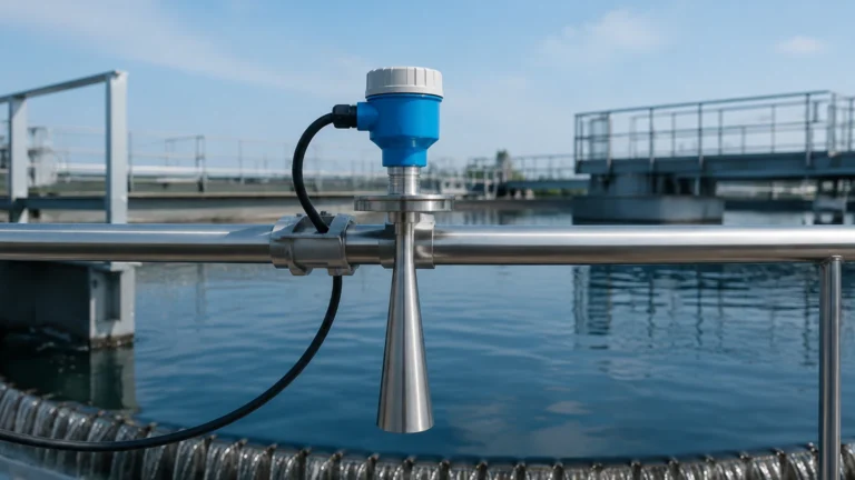
Cdc90
Cdc90
In the landscape of industrial process automation, precise level measurement is a cornerstone of operational efficiency and safety. Among the various technologies available, the CDC90 series represents a significant advancement in radar level measurement. Utilizing high-frequency 80GHz Frequency Modulated Continuous Wave (FMCW) technology, the CDC90 is engineered to handle complex measurement tasks that traditional ultrasonic or lower-frequency radar sensors often struggle with. This guide explores the technical foundations, application engineering, and selection criteria for implementing CDC90 technology in modern industrial environments.
Understanding the Measurement Principle: 80GHz FMCW Radar
The CDC90 operates on the principle of Frequency Modulated Continuous Wave (FMCW) radar. Unlike pulse radar, which measures the time-of-flight of a single microwave pulse, FMCW radar transmits a continuous signal with a frequency that varies linearly over time (a frequency sweep or "chirp").
The FMCW Process
1. Transmission: The CDC90 antenna emits a continuous microwave signal. The frequency of this signal increases over a specific bandwidth.
2. Reflection: The signal travels to the surface of the medium (liquid or solid) and is reflected back toward the sensor.
3. Mixing: The reflected signal is received by the antenna. Because the transmitter is constantly changing its frequency, there is a frequency difference between the transmitted signal and the received signal at any given moment.
4. Signal Processing: This frequency difference (beat frequency) is directly proportional to the distance between the sensor and the material surface. Fast Fourier Transform (FFT) algorithms then convert this frequency data into a precise distance measurement.
The Advantage of 80GHz Frequency
The move from traditional 6GHz or 26GHz radar to the 80GHz frequency used by the CDC90 offers several technical benefits:
* Narrow Beam Angle: High frequency allows for a much smaller beam angle (typically 3° to 6°). This is crucial for avoiding internal tank obstructions like agitators, heating coils, or ladders.
* Higher Resolution: The wider bandwidth available at 80GHz enables better signal separation, allowing the sensor to distinguish between the actual material surface and false echoes from dust or build-up.
* Smaller Antenna Size: Higher frequencies require smaller physical antennas, making the CDC90 easier to install on small process connections (as small as G1" or 1.5" flanges).
Key Features of the CDC90 Series
The CDC90 is designed for versatility across different media types. Whether measuring corrosive chemicals or abrasive bulk solids, the instrument provides a set of features tailored for reliability.
Enhanced Signal Sensitivity
With a high dynamic range, the CDC90 can detect signals from materials with low dielectric constants (εr). This makes it suitable for measuring hydrocarbons, plastic pellets, and dry powders that were previously difficult for radar sensors to track accurately.
Dust and Vapor Penetration
One of the primary challenges in silos is heavy dust during filling. The 80GHz signal of the CDC90 has superior penetration capabilities compared to ultrasonic sensors. It is less affected by air temperature fluctuations, pressure changes, or heavy steam, ensuring a stable output in volatile environments.
Non-Contact Measurement
As a non-contact instrument, the CDC90 does not come into physical contact with the medium. This reduces maintenance requirements, eliminates the risk of sensor corrosion, and prevents contamination of the process material.
Technical Specifications and Selection Table
Choosing the correct CDC90 configuration requires an understanding of the process conditions. The following table outlines the general parameters for standard CDC90 models.
| Feature | CDC90-L (Liquid Version) | CDC90-S (Solids Version) |
| :— | :— | :— |
| Measurement Range | Up to 30 meters | Up to 120 meters |
| Frequency | 76 GHz – 81 GHz | 76 GHz – 81 GHz |
| Measurement Accuracy | ±2 mm | ±5 mm |
| Beam Angle | 3° (depending on antenna) | 3° – 8° |
| Process Temperature | -40°C to +150°C (Standard) | -40°C to +250°C (High Temp) |
| Process Pressure | -0.1 to 2.0 MPa | -0.1 to 0.1 MPa (Atmospheric) |
| Output Signal | 4-20mA / HART / RS485 Modbus | 4-20mA / HART / RS485 Modbus |
| Enclosure Rating | IP67 / IP68 | IP67 |
Application Engineering: Where to Use CDC90
The CDC90 is particularly effective in industries where precision and uptime are non-negotiable. For more detailed product specifications and technical support, engineers can Review product options and application support at the Welk Main Page.
1. Bulk Solids and Silos
In the cement, mining, and grain industries, silos are often tall and narrow. The narrow beam of the CDC90 prevents interference from the silo walls. Furthermore, the high-frequency signal can track the "angle of repose" (the slope of the solid material) more effectively than lower-frequency alternatives.
2. Chemical Processing
For tanks containing acids, alkalis, or solvents, the CDC90 can be equipped with PTFE-lined antennas. This provides total chemical resistance while maintaining high-precision measurement through the vapor space.
3. Water and Wastewater Treatment
In open-channel flow or sump level monitoring, the CDC90 provides a maintenance-free alternative to ultrasonic sensors. It is unaffected by wind, ambient noise, or surface foam, which often cause "loss of echo" in ultrasonic devices.
4. High-Pressure and High-Temperature Vessels
Specialized versions of the CDC90 utilize ceramic seals or cooling fins to operate in extreme environments, such as bitumen storage or reactor vessels in petrochemical plants.
Installation Guidelines and Best Practices
Proper installation is critical to maximizing the performance of the CDC90. While the 80GHz technology is forgiving, following engineering best practices will ensure long-term stability.
Positioning
* Avoid the Center: Do not install the sensor in the exact center of a cylindrical tank. This can lead to multiple reflections from the tank walls that converge at the center, creating a false signal.
* Distance from Wall: Maintain a minimum distance from the tank wall (typically 200mm to 500mm depending on height) to prevent side-lobe interference.
* Inflow Stream: Ensure the radar beam does not intersect the path of the incoming material. Measuring the turbulence of a filling stream will result in erratic readings.
Mounting and Alignment
* Nozzle Height: The antenna should ideally extend slightly beyond the mounting nozzle to prevent "ringing" or interference from the nozzle edge. If a long nozzle is required, ensure the nozzle interior is smooth.
* Leveling: For solids measurement, an adjustable flange (aiming kit) is often recommended. This allows the user to point the radar beam at the discharge outlet or the center of the material pile to get the most representative average level.
Obstructions
Even with a 3° beam angle, large internal obstructions can cause issues. If an obstruction is unavoidable, the CDC90's software typically allows for "False Echo Suppression," where the device learns the fixed reflections and ignores them during operation.

Limitations and Considerations
While the CDC90 is a highly capable instrument, certain physical limitations must be acknowledged:
1. Heavy Foam: Extremely dense, thick foam (like shaving cream) can absorb the microwave signal. While 80GHz radar is better at penetrating light foam than ultrasonic, very thick foam may require a guided wave radar or a different measurement approach.
2. Extremely Low Dielectric Constants: Materials with a dielectric constant (εr) below 1.4 (such as certain liquefied gases) may reflect very little energy. In these cases, a stilling well or a specialized high-sensitivity configuration is necessary.
3. Vacuum Conditions: While radar works in a vacuum (unlike ultrasonic), the mechanical seals of the instrument must be rated for the specific vacuum levels of the vessel.
Maintenance and Troubleshooting
The CDC90 is designed for minimal maintenance. However, periodic checks can prevent unexpected downtime.
* Antenna Cleaning: In applications with high moisture and dust, a crust may form on the antenna lens. While the CDC90 can "see through" some build-up, heavy encrustation will eventually attenuate the signal. Many CDC90 units feature a simplified lens design that is easy to wipe clean or can be equipped with an air-purge system.
* Signal Strength Monitoring: Most digital CDC90 units provide a signal-to-noise ratio or "echo confidence" value. Monitoring this via HART or Modbus can provide an early warning if the environment is becoming too dusty or if the antenna needs cleaning.
Frequently Asked Questions (FAQ)
Q: Can the CDC90 measure through a plastic tank lid?
A: Yes. Because microwaves can penetrate non-conductive materials, the CDC90 can often measure the level inside a plastic or fiberglass tank without a hole being cut in the lid, provided the material is not too thick or reinforced with carbon fiber.
Q: How does the CDC90 handle agitators?
A: The narrow beam angle usually allows the CDC90 to be positioned to miss the agitator blades. If the beam does hit the blades, the software’s false echo suppression can filter out the intermittent reflections from the moving parts.
Q: What is the difference between CDC90 and 26GHz radar?
A: The primary difference is the beam angle and the antenna size. A 26GHz radar typically has a beam angle of 8° to 20°, which requires more clear space. The CDC90’s 80GHz signal is more focused, making it better for narrow silos and tanks with many internal structures.
Q: Is calibration required?
A: The CDC90 is factory-calibrated. On-site setup involves entering the tank height (4mA point) and the full level (20mA point). No "wet calibration" (filling and emptying the tank) is required, which saves significant time during commissioning.
Conclusion
The CDC90 high-frequency radar level meter is a robust solution for the demanding requirements of modern industrial processing. By leveraging 80GHz FMCW technology, it overcomes the limitations of traditional level measurement methods, offering higher precision, easier installation, and greater resistance to environmental interference. For engineers looking to optimize their level control systems, understanding the nuances of beam angles, dielectric constants, and proper mounting is essential. For further technical documentation and to explore the full range of level measurement instruments, visit the Main Page to find the right solution for your specific application.