Frequency of Radar Level Transmitter
Frequency of Radar Level Transmitter: A Technical Engineering Guide
In the field of industrial process automation, selecting the correct instrumentation is vital for operational safety, efficiency, and accuracy. Among the various technologies available, Radar Level Meters have become the gold standard for non-contact level measurement in both liquid and solid applications. However, the performance of these instruments is fundamentally dictated by the operating frequency. Choosing the right frequency of radar level transmitter is not merely a matter of cost; it is a technical decision that affects beam angle, signal reflection, and the ability to penetrate environmental interference like foam, dust, or steam.
This guide explores the engineering principles behind radar frequency, compares the common frequency bands used in modern industry, and provides practical selection criteria for engineers and procurement professionals.
Measurement Principles of Radar Level Technology
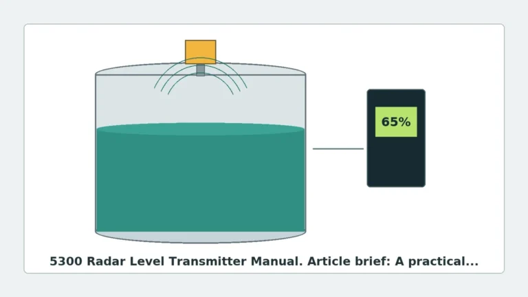
Before discussing frequency, it is essential to understand how radar level transmitters function. These devices utilize electromagnetic waves—specifically microwaves—to measure the distance from the sensor to the surface of the medium. The two primary methods of measurement are Pulse Radar and Frequency Modulated Continuous Wave (FMCW).
Pulse Radar
Pulse radar transmitters emit a microwave signal in short, periodic bursts. The instrument measures the time it takes for the pulse to travel to the surface and return to the receiver. This is known as Time of Flight (ToF). The distance is calculated using the formula:
Distance = (Speed of Light × Time of Flight) / 2
Frequency Modulated Continuous Wave (FMCW)
FMCW radar, which is increasingly common in high-frequency 80GHz transmitters, emits a continuous signal with a constantly changing frequency. As the signal reflects off the medium and returns, it is compared to the signal currently being emitted. The difference in frequency (the "beat frequency") is directly proportional to the distance. FMCW offers higher resolution and better signal-to-noise ratios compared to traditional pulse radar.
The Role of Frequency
The frequency of radar level transmitter refers to the number of wave cycles per second, measured in Hertz (Hz). In industrial applications, these typically range from 6 GHz to 120 GHz. The frequency determines the wavelength ($\\lambda$), where $\\lambda = c / f$ (c being the speed of light). A higher frequency results in a shorter wavelength, which fundamentally changes how the radar beam interacts with the environment and the process connection.
—
Comparison of Radar Frequency Bands
Industrial radar transmitters are generally categorized into three main frequency bands: C-band (low frequency), K-band (mid-frequency), and W-band (high frequency).
1. Low Frequency (6 GHz – 10 GHz)
Often referred to as C-band radar, these transmitters have long wavelengths (approximately 30 mm to 50 mm).
* Advantages: The primary benefit of low frequency is its ability to penetrate heavy steam, foam, and atmospheric condensation. Because the wavelength is relatively large, it is less affected by small particles or surface turbulence.
* Limitations: Low-frequency radar requires a very large antenna (often 150 mm to 250 mm) to achieve a focused beam. A wide beam angle increases the risk of interference from tank internal structures like agitators, ladders, or heating coils.
2. Mid-Frequency (24 GHz – 26 GHz)
K-band radar is the traditional "workhorse" of the industrial sector. It offers a balance between antenna size and signal focus.
* Advantages: It provides a narrower beam than 6 GHz models while remaining relatively affordable. It is suitable for a wide range of liquids and some solids.
* Limitations: While better than low-frequency models, 26 GHz radar can still struggle in narrow tanks or vessels with complex internal geometries. It is also more sensitive to heavy foam than C-band units.
3. High Frequency (76 GHz – 81 GHz)
High-frequency radar, or W-band, represents the current state-of-the-art in level measurement. With wavelengths around 3 mm to 4 mm, it offers significant technical advantages.
* Advantages: The most notable advantage is the extremely narrow beam angle (often as low as 3°). This allows the signal to bypass internal obstructions and makes it ideal for tall, narrow silos or tanks with many internals. Small antenna sizes (as small as 20 mm) allow for installation on small process connections.
* Limitations: High-frequency signals are more easily attenuated by heavy steam or thick, dense foam compared to low-frequency signals.
—
Practical Selection Table
| Feature | 6 GHz – 10 GHz | 24 GHz – 26 GHz | 80 GHz | 120 GHz (Emerging) |
| :— | :— | :— | :— | :— |
| Beam Angle | Wide (approx. 20° – 30°) | Medium (approx. 8° – 12°) | Narrow (approx. 3° – 6°) | Ultra-Narrow (< 3°) |
| Antenna Size | Large (DN150+) | Medium (DN50 – DN100) | Small (DN20 – DN50) | Miniature |
| Foam/Steam Resistance | Excellent | Moderate | Low to Moderate | Low |
| Dust Penetration | Good | Moderate | Excellent (for solids) | Excellent |
| Accuracy | ±5 mm to ±10 mm | ±2 mm to ±5 mm | ±1 mm | < ±1 mm |
| Common Application | Turbulent liquids, heavy steam | General storage tanks | Solids, narrow silos, small vessels | High-precision laboratory/small scale |
—
Engineering Installation Considerations
When selecting the frequency of radar level transmitter, engineers must account for the physical constraints of the installation site.
Beam Angle and Nozzle Interference
The beam angle is inversely proportional to the frequency and the antenna diameter. A narrow beam (high frequency) is critical when the transmitter is mounted near the tank wall or near internal obstructions. If the beam hits a ladder or a pipe, it creates a "false echo." While software can often "mask" these echoes, it reduces the overall reliability of the measurement.
The "Ringing" Effect and Dead Zones
Every radar transmitter has a "dead zone" (or blocking distance) near the antenna where measurement is not possible. High-frequency 80GHz radars typically have much smaller dead zones than 6GHz or 26GHz models because the shorter wavelength reduces the "ringing" effect (residual energy vibrating in the antenna after transmission).
Dielectric Constant (εr)
The reflectivity of the medium is determined by its dielectric constant. Materials with high εr (like water, εr ≈ 80) reflect signals strongly. Materials with low εr (like plastic pellets or oils, εr < 2) reflect signals weakly. High-frequency radar is generally better at detecting low-dielectric materials because the higher energy density of the focused beam provides a stronger return signal from the surface.
Nozzle Height and Diameter
For high-frequency radar, the nozzle height is less of a concern because the narrow beam can pass through long, narrow nozzles without reflecting off the nozzle walls. For low-frequency radar, the antenna must usually extend below the bottom of the nozzle to prevent signal interference.
—
Application-Specific Recommendations
1. Bulk Solids and Powders
For solids, 80 GHz is almost always the preferred choice. Solids surfaces are rarely flat; they form cones (repose angles) that scatter radar signals. The high frequency and narrow beam of 80 GHz radar ensure that enough energy is reflected directly back to the sensor, even on uneven surfaces. Furthermore, it excels in dusty environments where the dust particles are much smaller than the 3mm wavelength.
2. Chemical Storage with Agitators
In vessels containing agitators or mixers, a 26 GHz or 80 GHz transmitter is recommended. The narrow beam can be positioned to "look" between the agitator blades and the tank wall, avoiding false reflections that would plague a 6 GHz unit.
3. Water and Wastewater Treatment
For open-channel flow or large basin level measurement, 26 GHz is often the most cost-effective solution. However, if the sensor is mounted in a stilling well or a narrow bypass pipe, 80 GHz is superior due to the lack of interference from the pipe walls.
4. High-Pressure Steam Applications
In boiler drums or high-temperature reactors where steam is dense, a 6 GHz or 10 GHz radar is often the most reliable choice. The longer wavelength is less likely to be scattered by water droplets in the vapor space.
—
Frequently Asked Questions (FAQs)
Q: Does a higher frequency always mean better accuracy?
A: Generally, yes. Higher frequency (FMCW) radar allows for a wider bandwidth, which results in better linear resolution and higher accuracy (often up to ±1 mm). However, for simple water storage, the ±5 mm accuracy of a lower frequency unit is usually sufficient.
Q: Can 80 GHz radar measure through foam?
A: It depends on the foam type. Dry, light foam can often be penetrated. However, thick, wet, or dense foam (like that found in some fermentation processes) will reflect or absorb the 80 GHz signal. In these cases, a 6 GHz radar or a contact-based technology like a magnetic level gauge or hydrostatic transmitter may be required.
Q: Is 120 GHz radar better than 80 GHz?
A: 120 GHz offers even narrower beams and smaller antennas, but it is a newer technology and typically more expensive. It is best reserved for extremely small vessels or applications requiring sub-millimeter precision.
Q: How do I choose the antenna type for my frequency?
A: Horn antennas are common for 26 GHz. For 80 GHz, lens antennas (made of PEEK or PTFE) are standard because they are flush-mounted, easy to clean, and highly resistant to chemical corrosion.
—
Summary for International Buyers
When sourcing Radar Level Meters, international buyers should confirm the following technical parameters with the manufacturer to ensure the frequency of radar level transmitter is appropriate for the site:
1. Medium Properties: What is the dielectric constant (εr)? Is there foam, dust, or steam?
2. Vessel Geometry: What is the tank height and diameter? Are there internal obstructions?
3. Process Connection: What is the size of the existing flange or thread? (High frequency allows for smaller connections).
4. Environmental Conditions: What are the operating temperature and pressure? (This influences antenna material selection).
By matching the radar frequency to the specific physical and chemical characteristics of the process, engineers can ensure a maintenance-free installation with high data integrity. Whether it is the robust penetration of 6 GHz or the precision focus of 80 GHz, understanding the frequency is the first step toward successful level automation.